Pulse Width Modulation (PWM) is a technique for encoding information into the width of periodic pulses. A digital output rapidly toggles between high and low states; the fraction of time it spends high — the duty cycle — effectively controls the average power delivered to the load. This makes PWM the standard interface for motor speed control, LED brightness dimming, voltage regulation, servo positioning, and fan speed management in embedded systems.
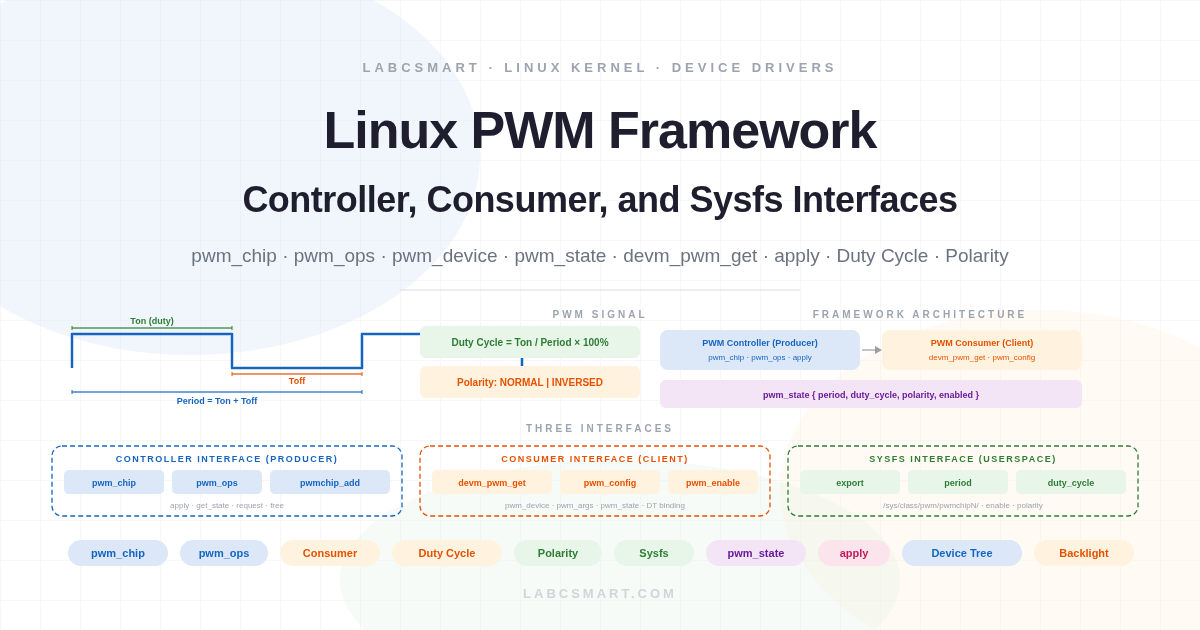
The Linux kernel provides a dedicated PWM framework that separates hardware drivers (controllers/producers) from the code that uses PWM signals (consumers). This separation means a single backlight driver works with any SoC’s PWM hardware, and a single PWM controller driver serves any consumer — motor, LED, or regulator. This article covers the PWM signal fundamentals, the controller driver interface (struct pwm_chip, struct pwm_ops, registration), the consumer interface (pwm_get, pwm_apply_state, device tree binding), and the sysfs userspace interface.
Table of Contents
- PWM Signal Fundamentals
- The Linux PWM Framework Architecture
- PWM Controller Driver Interface
- PWM Consumer Driver Interface
- PWM Userspace Interface with sysfs
- Summary
PWM Signal Fundamentals
The PWM Signal
A PWM signal is a periodic rectangular wave that alternates between a high voltage level (logic 1) and a low voltage level (logic 0). Each cycle consists of two phases: Ton (the time the signal stays high) and Toff (the time the signal stays low). The period is the total duration of one complete cycle: period = Ton + Toff. The frequency is the inverse of the period: frequency = 1 / period.
Figure 1 — PWM signal: the period is the total cycle time, the duty cycle is the fraction spent high.
The period is expressed in nanoseconds in the Linux PWM framework. A period of 20,000,000 ns corresponds to 20 ms, which gives a frequency of 50 Hz — the standard for servo motors. A period of 1,000,000 ns (1 ms) gives 1 kHz, typical for LED dimming. The duty cycle is also expressed in nanoseconds (not as a percentage): for a 50% duty cycle on a 20 ms period, you set duty_cycle = 10000000.
Duty Cycle and Polarity
The duty cycle determines the effective output. At 0% duty, the signal is always low (load off). At 100% duty, the signal is always high (full power). Intermediate values provide proportional control — 25% delivers roughly a quarter of full power to the load (averaged over time).
Figure 2 — Top: duty cycle controls average power (25%, 50%, 75%). Bottom: normal vs inversed polarity.
Polarity defines which phase is the “active” phase. With normal polarity (PWM_POLARITY_NORMAL), the duty cycle corresponds to the high portion of the signal. With inversed polarity (PWM_POLARITY_INVERSED), the duty cycle corresponds to the low portion. Inversed polarity is useful when the hardware inverts the signal externally (e.g., an active-low LED driver).
The Linux PWM Framework Architecture
The PWM framework follows the producer-consumer model used throughout the kernel. PWM controller drivers (producers) register their hardware capabilities with the framework. Consumer drivers request PWM channels by name or device tree reference and configure them through a uniform API. The framework handles matching, reference counting, and state management.
Figure 3 — PWM framework: consumers request channels through the core, which routes to the appropriate controller driver.
Both controller and consumer drivers include <linux/pwm.h>. Controller drivers live in drivers/pwm/. Consumer drivers live wherever their primary subsystem is (backlight in drivers/video/backlight/, LED in drivers/leds/, regulator in drivers/regulator/).
PWM Controller Driver Interface
The pwm_chip Structure
A PWM controller is represented by struct pwm_chip. This is the central structure that the controller driver fills during probe and registers with the framework. It describes the hardware: how many channels, what operations are supported, and how device tree specifiers are translated into PWM device references.
struct pwm_chip {
    struct device        *dev;         /* Parent device */
    const struct pwm_ops *ops;         /* Controller callbacks */
    int                  base;         /* First PWM number (-1 = auto) */
    unsigned int         npwm;         /* Number of PWM channels */
    struct pwm_device    *pwms;        /* Array of PWM devices (framework-allocated) */

    /* Device tree translation */
    struct pwm_device *(*of_xlate)(struct pwm_chip *chip,
                       const struct of_phandle_args *args);
    unsigned int of_pwm_n_cells;       /* Expected DT cells (usually 2 or 3) */
};
Key fields: dev is the parent platform/I2C/SPI device. ops points to the callback structure (covered next). npwm tells the framework how many channels this controller provides. base should be set to -1 for automatic numbering. The of_xlate hook translates device tree PWM specifiers into pwm_device pointers — if left NULL, the framework uses a default translator that expects 2 cells (channel index + period). The pwms array is allocated by the framework during registration; the driver does not allocate it.
Registration and unregistration use two functions. Both take a pointer to a filled-in pwm_chip.
int pwmchip_add(struct pwm_chip *chip);       /* Register controller */
int pwmchip_remove(struct pwm_chip *chip);    /* Unregister controller */

/* pwmchip_remove returns -EBUSY if any channel is still in use */
pwmchip_add() validates the chip structure, allocates the pwms array, and adds the chip to the global list. pwmchip_remove() returns -EBUSY if any channel is still requested by a consumer — unlike most framework removal functions, it can fail, so drivers must check its return value.
The pwm_ops Callbacks
The controller driver implements hardware operations through struct pwm_ops. The most important callback is apply, which atomically configures all PWM parameters (period, duty cycle, polarity, enable state) in a single call. Legacy drivers had separate config, enable, disable, and set_polarity callbacks, but these are deprecated — new drivers must use apply.
struct pwm_ops {
    int  (*request)(struct pwm_chip *chip, struct pwm_device *pwm);
    void (*free)(struct pwm_chip *chip, struct pwm_device *pwm);
    int  (*apply)(struct pwm_chip *chip, struct pwm_device *pwm,
                  const struct pwm_state *state);
    int  (*get_state)(struct pwm_chip *chip, struct pwm_device *pwm,
                      struct pwm_state *state);
    struct module *owner;
};
request and free are optional hooks for per-channel initialization and cleanup (e.g., enabling a channel-specific clock). apply is mandatory: it receives the desired state and must program the hardware accordingly. If the hardware cannot match the exact requested values, the driver should adjust to the closest supported configuration and update the state structure to reflect what was actually applied. get_state reads the current hardware configuration and fills the state structure — this is called during channel request so the framework knows the initial state. owner is always THIS_MODULE.
The pwm_state Structure
The pwm_state structure carries the complete configuration of a PWM channel in a single object. This is what flows between the framework, the consumer, and the controller driver.
struct pwm_state {
    u64 period;                    /* Total cycle time in nanoseconds */
    u64 duty_cycle;                /* Active time in nanoseconds */
    enum pwm_polarity polarity;    /* PWM_POLARITY_NORMAL or _INVERSED */
    bool enabled;                  /* Channel output active */
};
The duty_cycle must always be less than or equal to period. Both are in nanoseconds. The apply callback receives this structure as a const pointer; the driver reads the desired state from it and programs the hardware. The get_state callback fills this structure from hardware registers so the framework knows the actual configuration.
Complete Controller Driver Example
Here is a complete skeleton for a PWM controller driver that exposes three channels. The driver follows the standard pattern: define a private structure embedding pwm_chip, implement the pwm_ops callbacks, and register the chip in probe.
#include <linux/module.h>
#include <linux/of.h>
#include <linux/platform_device.h>
#include <linux/pwm.h>

struct my_pwm {
    struct pwm_chip chip;
    void __iomem *base;
    struct clk *clk;
};

static inline struct my_pwm *to_my_pwm(struct pwm_chip *chip)
{
    return container_of(chip, struct my_pwm, chip);
}

static int my_pwm_apply(struct pwm_chip *chip, struct pwm_device *pwm,
                         const struct pwm_state *state)
{
    struct my_pwm *priv = to_my_pwm(chip);

    /* Program period register */
    writel(div_u64(state->period, priv->clk_period_ns),
           priv->base + REG_PERIOD(pwm->hwpwm));

    /* Program duty cycle register */
    writel(div_u64(state->duty_cycle, priv->clk_period_ns),
           priv->base + REG_DUTY(pwm->hwpwm));

    /* Set polarity */
    if (state->polarity == PWM_POLARITY_INVERSED)
        my_pwm_set_bit(priv, REG_CTRL, BIT(pwm->hwpwm));
    else
        my_pwm_clear_bit(priv, REG_CTRL, BIT(pwm->hwpwm));

    /* Enable/disable */
    if (state->enabled)
        my_pwm_set_bit(priv, REG_EN, BIT(pwm->hwpwm));
    else
        my_pwm_clear_bit(priv, REG_EN, BIT(pwm->hwpwm));

    return 0;
}

static int my_pwm_get_state(struct pwm_chip *chip,
                             struct pwm_device *pwm,
                             struct pwm_state *state)
{
    struct my_pwm *priv = to_my_pwm(chip);

    state->period = readl(priv->base + REG_PERIOD(pwm->hwpwm))
                    * priv->clk_period_ns;
    state->duty_cycle = readl(priv->base + REG_DUTY(pwm->hwpwm))
                        * priv->clk_period_ns;
    state->polarity = (readl(priv->base + REG_CTRL) & BIT(pwm->hwpwm))
                      ? PWM_POLARITY_INVERSED : PWM_POLARITY_NORMAL;
    state->enabled = !!(readl(priv->base + REG_EN) & BIT(pwm->hwpwm));
    return 0;
}

static const struct pwm_ops my_pwm_ops = {
    .apply = my_pwm_apply,
    .get_state = my_pwm_get_state,
    .owner = THIS_MODULE,
};

static int my_pwm_probe(struct platform_device *pdev)
{
    struct my_pwm *priv;

    priv = devm_kzalloc(&pdev->dev, sizeof(*priv), GFP_KERNEL);
    if (!priv)
        return -ENOMEM;

    priv->base = devm_platform_ioremap_resource(pdev, 0);
    if (IS_ERR(priv->base))
        return PTR_ERR(priv->base);

    priv->clk = devm_clk_get_enabled(&pdev->dev, NULL);
    if (IS_ERR(priv->clk))
        return PTR_ERR(priv->clk);

    priv->chip.dev = &pdev->dev;
    priv->chip.ops = &my_pwm_ops;
    priv->chip.npwm = 3;           /* 3 PWM channels */
    priv->chip.base = -1;          /* Auto-assign numbering */

    return pwmchip_add(&priv->chip);
}

static void my_pwm_remove(struct platform_device *pdev)
{
    struct my_pwm *priv = platform_get_drvdata(pdev);
    pwmchip_remove(&priv->chip);
}

static const struct of_device_id my_pwm_dt_ids[] = {
    { .compatible = "vendor,my-pwm" },
    { }
};
MODULE_DEVICE_TABLE(of, my_pwm_dt_ids);

static struct platform_driver my_pwm_driver = {
    .driver = {
        .name = "my-pwm",
        .of_match_table = my_pwm_dt_ids,
    },
    .probe = my_pwm_probe,
    .remove = my_pwm_remove,
};
module_platform_driver(my_pwm_driver);

MODULE_LICENSE("GPL");
The apply callback programs all four parameters (period, duty cycle, polarity, enable) atomically. The get_state callback reads them back from hardware registers. The hwpwm field in pwm_device is the channel index local to this chip (0, 1, or 2 for a 3-channel controller).
Controller Device Tree Binding
The PWM controller node must include #pwm-cells, which tells the framework how many cells each PWM specifier uses. With 2 cells: channel index + period. With 3 cells: channel index + period + flags (for polarity). The controller exposes numbered channels that consumers reference by index.
Figure 4 — A PWM controller chip with its numbered channels, each independently configurable.
my_pwm: pwm@40010000 {
    compatible = "vendor,my-pwm";
    reg = <0x40010000 0x1000>;
    clocks = <&rcc PWM_CLK>;
    #pwm-cells = <3>;   /* channel, period_ns, flags */
};
When #pwm-cells is 2, the default of_xlate handler is used and the polarity defaults to normal. When #pwm-cells is 3, the third cell can include PWM_POLARITY_INVERTED (defined in <dt-bindings/pwm/pwm.h>).
PWM Consumer Driver Interface
The pwm_device Structure
From the consumer’s perspective, a PWM channel is represented by struct pwm_device. Consumers never allocate this structure — the framework returns a pointer to it when a channel is requested.
struct pwm_device {
    const char     *label;        /* Name for debugging */
    unsigned long  flags;         /* Framework-internal flags */
    unsigned int   hwpwm;         /* Channel index on the chip */
    unsigned int   pwm;           /* System-global PWM number */
    struct pwm_chip *chip;        /* Owning controller */
    struct pwm_args args;         /* DT-specified initial config */
    struct pwm_state state;       /* Last applied state */
};
The args field holds the initial configuration from the device tree (period and polarity from the PWM specifier). The state field tracks the last configuration applied via pwm_apply_state(). The consumer uses pwm_device as an opaque handle — it passes it to all PWM API functions.
Requesting and Releasing PWM Devices
Consumers obtain a PWM channel with pwm_get() or its managed variant devm_pwm_get(). The managed version is strongly recommended: the framework automatically releases the channel when the consumer device is removed, even on error paths.
/* Managed request (preferred -- auto-released on device removal) */
struct pwm_device *devm_pwm_get(struct device *dev, const char *con_id);

/* Manual request/release (only if managed is not suitable) */
struct pwm_device *pwm_get(struct device *dev, const char *con_id);
void pwm_put(struct pwm_device *pwm);
The con_id parameter matches the pwm-names property in the device tree. If a consumer has only one PWM channel, con_id can be NULL (the first channel is returned). If the consumer uses multiple channels, pwm-names provides the mapping so pwm_get() returns the correct one. Neither pwm_get() nor pwm_put() can be called from atomic context — the framework uses mutexes internally.
Configuring and Controlling PWM
The modern API uses pwm_apply_state() to set all parameters atomically. This replaces the legacy pwm_config(), pwm_enable(), and pwm_disable() functions (which are still available but deprecated for new code).
Figure 5 — pwm_apply_state routes through the core to the controller’s apply callback.
/* Modern API: set all parameters atomically */
int pwm_apply_state(struct pwm_device *pwm,
                    const struct pwm_state *state);

/* Helper to read current state */
void pwm_get_state(struct pwm_device *pwm, struct pwm_state *state);

/* Initialize state from device tree args */
void pwm_init_state(struct pwm_device *pwm, struct pwm_state *state);

/* Legacy API (deprecated, but still functional) */
int pwm_config(struct pwm_device *pwm, int duty_ns, int period_ns);
int pwm_enable(struct pwm_device *pwm);
void pwm_disable(struct pwm_device *pwm);
pwm_apply_state() validates that duty_cycle <= period, then calls the controller’s apply callback. pwm_init_state() is a convenience that fills a pwm_state from the device tree arguments (the period and polarity specified in the pwms property). The typical consumer pattern is: get the PWM, init state from DT, set the desired duty cycle and enable flag, then apply.
Consumer Device Tree Binding
PWM consumers reference their channels through the pwms property, which contains a phandle to the controller followed by the PWM specifier (channel index, period, optional flags). The pwm-names property provides string names for each channel. The following diagram shows how the device tree wires consumers to specific channels on the controller.
Figure 5 — Device tree wiring: consumers reference specific controller channels via phandle + index. pwm-names maps to devm_pwm_get() calls.
/* Controller */
my_pwm: pwm@40010000 {
    compatible = "vendor,my-pwm";
    #pwm-cells = <3>;
    /* ... */
};

/* Consumer: backlight using channel 0, 5ms period, inversed polarity */
backlight {
    compatible = "pwm-backlight";
    pwms = <&my_pwm 0 5000000 PWM_POLARITY_INVERTED>;
    pwm-names = "backlight";
    brightness-levels = <0 16 32 64 128 255>;
    default-brightness-level = <4>;
};

/* Consumer with multiple PWM channels */
motor_controller {
    compatible = "vendor,dual-motor";
    pwms = <&my_pwm 1 20000000 0>,   /* Motor A: channel 1, 20ms */
           <&my_pwm 2 20000000 0>;   /* Motor B: channel 2, 20ms */
    pwm-names = "motor-a", "motor-b";
};
In the PWM specifier, the first cell is the channel index (0-based, relative to the controller), the second is the period in nanoseconds, and the third (when #pwm-cells = 3) contains flags. The pwm-names property maps names to the pwms list in order: "motor-a" corresponds to the first entry, "motor-b" to the second. The driver uses devm_pwm_get(dev, "motor-a") to request the correct channel.
Complete Consumer Example
A PWM-controlled LED backlight driver showing the complete lifecycle: request, configure from device tree parameters, adjust duty cycle, and enable.
static int backlight_probe(struct platform_device *pdev)
{
    struct pwm_device *pwm;
    struct pwm_state state;
    int ret;

    /* Request PWM channel (managed -- auto-released) */
    pwm = devm_pwm_get(&pdev->dev, "backlight");
    if (IS_ERR(pwm))
        return dev_err_probe(&pdev->dev, PTR_ERR(pwm),
                             "Failed to get PWM\n");

    /* Initialize state from device tree (period + polarity) */
    pwm_init_state(pwm, &state);

    /* Set 50% brightness (half the period as duty cycle) */
    state.duty_cycle = state.period / 2;
    state.enabled = true;

    /* Apply atomically */
    ret = pwm_apply_state(pwm, &state);
    if (ret)
        return dev_err_probe(&pdev->dev, ret,
                             "Failed to apply PWM state\n");

    platform_set_drvdata(pdev, pwm);
    return 0;
}

static void backlight_remove(struct platform_device *pdev)
{
    struct pwm_device *pwm = platform_get_drvdata(pdev);
    struct pwm_state state;

    /* Disable before removal */
    pwm_get_state(pwm, &state);
    state.enabled = false;
    state.duty_cycle = 0;
    pwm_apply_state(pwm, &state);
    /* devm handles pwm_put automatically */
}
The pattern is clean: pwm_init_state reads the DT-specified period and polarity, the driver sets the duty cycle and enables the output, and pwm_apply_state programs the hardware in one atomic call. On removal, the driver disables the output before the managed release happens.
PWM Userspace Interface with sysfs
The PWM framework exposes a sysfs interface at /sys/class/pwm/ for userspace control without writing a kernel driver. This is useful for prototyping, testing, and simple use cases. Each registered PWM chip creates a pwmchipN directory.
Figure 6 — sysfs PWM hierarchy: chip directory with export/unexport, channel directory with configuration files.
Exporting a channel creates a pwmN subdirectory with four files: period (nanoseconds), duty_cycle (nanoseconds, must be <= period), polarity (“normal” or “inversed”), and enable (0 or 1). The polarity should only be changed while the channel is disabled.
Here is a complete sysfs session controlling a PWM-driven LED at 1 kHz with 25% brightness.
# Discover available chips
ls /sys/class/pwm/
# pwmchip0  pwmchip3

# Check how many channels chip 0 provides
cat /sys/class/pwm/pwmchip0/npwm
# 4

# Export channel 0
echo 0 > /sys/class/pwm/pwmchip0/export

# Set period to 1ms (1 kHz)
echo 1000000 > /sys/class/pwm/pwmchip0/pwm0/period

# Set duty cycle to 25% (250us)
echo 250000 > /sys/class/pwm/pwmchip0/pwm0/duty_cycle

# Enable output
echo 1 > /sys/class/pwm/pwmchip0/pwm0/enable

# Read back current state
cat /sys/class/pwm/pwmchip0/pwm0/period     # 1000000
cat /sys/class/pwm/pwmchip0/pwm0/duty_cycle  # 250000
cat /sys/class/pwm/pwmchip0/pwm0/enable      # 1

# Adjust to 75% brightness
echo 750000 > /sys/class/pwm/pwmchip0/pwm0/duty_cycle

# Disable and unexport when done
echo 0 > /sys/class/pwm/pwmchip0/pwm0/enable
echo 0 > /sys/class/pwm/pwmchip0/unexport
The sysfs writes translate directly to pwm_apply_state() calls inside the kernel. Setting period and duty_cycle builds a pwm_state and calls the controller’s apply callback. This is the same code path as in-kernel consumers — the sysfs interface is just a different entry point into the same framework.
Summary
PWM encodes control information in pulse width: the duty cycle (fraction of time the signal is high) determines the average power delivered to the load. The Linux PWM framework cleanly separates controllers (producers) from consumers. Controller drivers implement struct pwm_ops — primarily the apply callback for atomic configuration and get_state for reading hardware state — and register via pwmchip_add(). Consumer drivers request channels with devm_pwm_get(), initialize state from device tree parameters with pwm_init_state(), and apply configurations atomically with pwm_apply_state(). The sysfs interface at /sys/class/pwm/ provides userspace control for prototyping and testing without writing a kernel driver.