When you press the power button on an embedded Linux device, a complex chain of software executes before the first line of kernel code ever runs. This article walks through the entire boot process, from the moment the processor leaves reset to the point where Linux takes over — with a deep dive into U-Boot, ARM Trusted Firmware (TF-A), OP-TEE, and the ARM exception level model that governs it all.
Table of Contents
- Why Does a System Need a Bootloader?
- The Boot Chain Concept
- Common Bootloaders in Embedded Linux
- Brief History of U-Boot
- U-Boot Release Cycle
- U-Boot Key Features
- What U-Boot Does at Boot Time
- Typical ARM Boot Flow
- ARM Exception Levels
- ARM TrustZone
- ARM Trusted Firmware Boot Stages
- TF-A (BL31): The Secure Monitor at Runtime
- PSCI: CPU Power Management
- OP-TEE in the Boot Chain
- Secure Memory Carve-Outs
- SPL FIT Image: Packaging All Firmware
- The Handoff to Linux
Why Does a System Need a Bootloader?
When a processor powers on, it cannot run an operating system directly. RAM is not yet initialized, storage devices are not configured, and the kernel image must be loaded into memory before it can execute. A bootloader bridges the gap between hardware reset and the OS: it initializes critical hardware (clocks, DRAM, storage) and then loads and starts the operating system kernel.
Figure 1 — The boot chain from power-on to kernel entry.
This clean handoff model also gives engineers a well-defined intervention point: if the system fails to boot, the bootloader shell provides direct hardware access before the kernel is ever involved.
The Boot Chain Concept
Modern embedded systems rarely boot in a single step. At power-on, the only memory available is a small internal SRAM — typically 128 to 256 KB on most ARM SoCs. DRAM requires a complex initialization and training sequence before it is usable. This creates a chicken-and-egg problem: you need to run code to initialize DRAM, but you need memory to run code.
The solution is a multi-stage boot chain where each stage runs in a progressively more capable environment. Each stage is small enough to fit in what is available at the time, and each prepares the ground for the next. This staged approach is also a security boundary — each stage can verify the next before handing over control.
Figure 2 — Multi-stage boot: each stage runs in a more capable environment.
The chain of trust starts here: each stage can cryptographically verify the next before handing over control, which is the foundation of secure boot and measured boot on production hardware.
Common Bootloaders in Embedded Linux
U-Boot is the de facto standard bootloader for embedded Linux. It supports ARM, RISC-V, MIPS, x86, PowerPC, and more. It is actively maintained with quarterly releases and provides a rich command-line interface for interactive development.
Other notable bootloaders include Barebox, which features a modern Linux-like design with a device model, and GRUB, which dominates the x86/UEFI desktop and server space. On RISC-V, OpenSBI plays a role analogous to TF-A on ARM — providing the runtime supervisor binary interface between the OS and machine-mode firmware.
Brief History of U-Boot
U-Boot originated from the PPCBoot project in the year 2000, initially targeting PowerPC embedded processors only. It was renamed to Das U-Boot in 2002 (a nod to the famous submarine film) and expanded to support ARM, MIPS, and many other architectures. The project is maintained by DENX Software Engineering, led by Wolfgang Denk. The source code is hosted at source.denx.de/u-boot/u-boot, and releases follow a YYYY.MM naming convention.
U-Boot Release Cycle
Figure 3 — U-Boot quarterly release timeline.
U-Boot releases happen quarterly — in January, April, July, and October. Each cycle has a merge window followed by stabilization, with release candidates (-rc1 to -rc4) published along the way. The current stable release at time of writing is 2025.04. Specific subsystems (ARM, RISC-V, DM, network, etc.) are each maintained by a dedicated custodian.
U-Boot Key Features
U-Boot provides hardware initialization and bring-up for DRAM controllers, clocks, pinmux, storage, and network interfaces. It can also drive display output for splash screens on supported boards. For loading the kernel, U-Boot supports a wide range of boot media: SD/eMMC, NAND/NOR flash, SPI, USB, TFTP, and UART download. It understands FIT images, Android Boot images, and EFI boot. On top of all this, U-Boot offers a developer-friendly interactive command shell for development and debugging.
What U-Boot Does at Boot Time
U-Boot performs a well-defined initialization sequence where each step builds on the results of the previous one. If any step fails, the boot process halts and drops to the U-Boot shell. Understanding this sequence is essential for bring-up work and for debugging boot failures on new hardware.
Figure 4 — U-Boot’s initialization sequence.
Everything U-Boot does — clock setup, DRAM training, storage init, image loading — serves one objective: handing off to the operating system. The ultimate goal of this entire sequence is to produce a ready-to-run environment for the Linux kernel.
U-Boot vs. Bare-Metal Initialization
Without U-Boot, you would need to write custom initialization code: DRAM training sequences for each board, storage protocol initialization, and your own image loading and validation logic. U-Boot abstracts all of this complexity, providing tested, community-maintained drivers with board-specific details isolated in configuration files.
Typical ARM Boot Flow with U-Boot
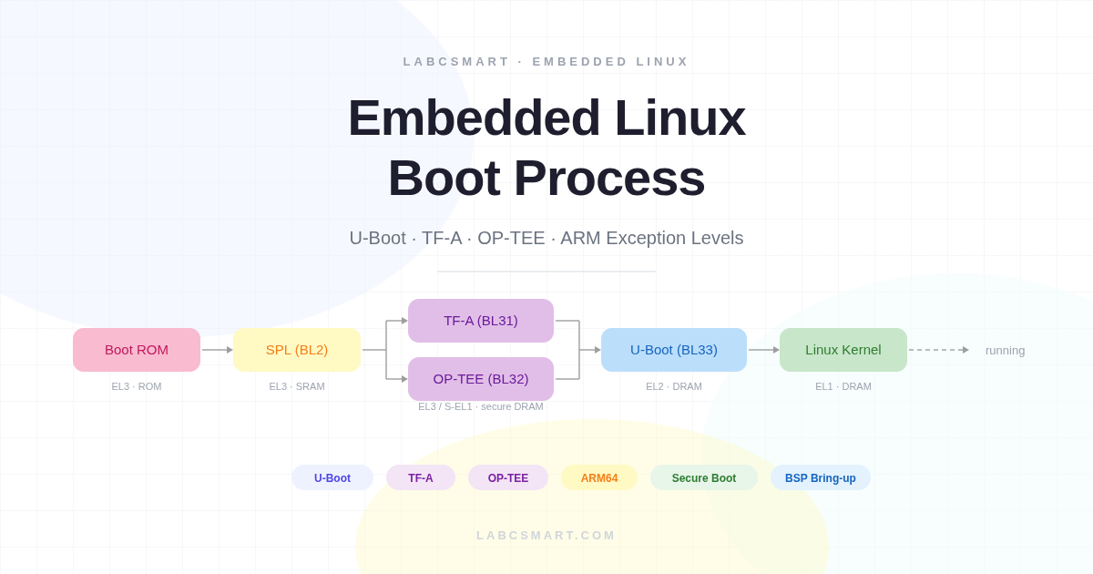
On a typical ARMv8 platform, the boot flow involves four distinct stages. The Boot ROM is fixed in silicon by the SoC manufacturer — completely immutable, the root of trust. It reads boot pin strapping to select the boot media and loads the SPL binary from that media into on-chip SRAM.
The SPL then initializes DRAM and loads the full U-Boot image. U-Boot takes over: it loads the kernel, DTB, and hands off to Linux. In secure boot configurations, TF-A and OP-TEE are inserted between SPL and U-Boot — covered in depth later in this article.
Figure 5 — Standard ARM boot flow: Boot ROM -> SPL → U-Boot → Linux.
The SPL size constraint shapes how it is compiled: minimal feature set, only the drivers needed to initialize DRAM and load the next stage. Anything else must wait for U-Boot proper, which has the full feature set available in DRAM.
ARM Exception Levels
Before diving into TF-A and secure boot, it is essential to understand how ARMv8-A manages software privilege. ARM defines four Exception Levels (EL0–EL3), where a higher number means more privilege and more hardware access. This hierarchy is enforced in silicon — there is no software workaround.
Each level is designed for a specific class of software: EL0 for user applications, EL1 for the OS kernel, EL2 for the hypervisor, and EL3 for the secure monitor. EL3 is special: it controls the boundary between the secure and normal worlds and is the only level that can perform a world switch.
Figure 6 — ARMv8-A defines four Exception Levels (EL0–EL3).
Transitions between exception levels follow strict rules. The CPU always starts at EL3 after reset — fixed in hardware. A binary does not choose its own exception level. Only code at a higher EL can drop you to a lower one via ERET. The only way to go up is to cause an exception: SMC traps from EL1/EL2 up to EL3, and HVC traps from EL1 up to EL2.
Exception Level Transitions: You Can Only Drop
Figure 7 – A binary does not choose its own exception level. You can only drop down via ERET or trap up via SMC/HVC.
A key concept: a binary does not choose its own exception level. The CPU starts at EL3 after reset — this is fixed in hardware. Only code running at a higher EL can drop you to a lower one, and there is no instruction to promote yourself to a higher EL. The only way to go up is to cause an exception: SMC traps from EL1/EL2 up to EL3 (for TF-A services), and HVC traps from EL1 up to EL2 (for hypervisor services).
How TF-A Sets U-Boot’s Exception Level
TF-A (BL31) runs at EL3 after SPL loads it. To launch U-Boot, BL31 writes SPSR_EL3 with the target EL2 mode bits, writes U-Boot’s entry address into ELR_EL3, and executes the ERET instruction. This atomically drops the CPU to EL2 and branches to U-Boot’s entry point. U-Boot simply wakes up at EL2 — it has no say in the matter. The same mechanism is used later when U-Boot drops Linux to EL1.
ARM TrustZone: Hardware Security Foundation
TrustZone is a hardware feature built into the ARM CPU and bus fabric that partitions the entire system into two parallel worlds: the normal world (non-secure) where Linux runs, and the secure world where OP-TEE and security-critical code execute. This partitioning is enforced in silicon — it is not a software abstraction.
Figure 8 – TrustZone partitions the system into Normal and Secure worlds.
Every bus transaction carries a secure/non-secure bit (the NS bit). The TZASC (TrustZone Address Space Controller) enforces memory isolation: secure memory regions are completely invisible to the normal world. Any normal-world attempt to access secure memory results in a bus fault.
The Secure Monitor at EL3 is the only gateway between the two worlds. The two worlds share the same physical CPU cores — the world switch is a context save and restore performed by TF-A. Normal-world code triggers it via the SMC instruction, which traps to EL3 where TF-A decides how to handle the request.
What Runs at Each Exception Level
Figure 9 — Each world has its own EL1 and EL0, running in parallel on shared physical CPU cores.
Each world has its own EL1 and EL0 running in parallel on the same physical cores: the normal world runs Linux at EL1 and user apps at EL0, while the secure world runs OP-TEE at S-EL1 and Trusted Applications at S-EL0. EL3 is neither normal nor secure — it controls both. U-Boot typically runs at EL2 (or EL1 if no hypervisor is needed).
The ARM Trusted Firmware Boot Stages
ARM Trusted Firmware defines a standard naming convention for boot stages, making it easier to reason about the secure boot flow across different SoC vendors. Understanding these stage names is important when reading TF-A documentation, BSP build systems, and FIT image configurations.
Figure 10 – TF-A boot stage naming: BL1 through BL33.
BL1 is the first code executed from ROM or secure flash, running at EL3. BL2 is the trusted boot loader that authenticates and loads the BL3x stages. BL31 is the runtime Secure Monitor that always stays in memory at EL3. On many SoCs, U-Boot SPL takes the role of BL2.
BL32 and BL33 are loaded by BL2 but run independently: BL32 is a secure OS like OP-TEE (optional, running at S-EL1), and BL33 is the first non-secure code — which is U-Boot proper, running at EL2.
ARM Trusted Firmware in the Full Boot Flow
BL1 and BL2 are transient: they run once and their memory is reclaimed once all BL3x stages are loaded. BL31 and BL32, however, are permanent residents in secure DRAM. They don’t have dedicated CPU cores of their own — when the normal world issues an SMC, the same core switches context to the secure world, handles the request, and returns. Their memory regions are marked secure and hidden from Linux.
Figure 11 — Complete ARM boot flow with exception level transitions.
On most ARMv8 SoCs, U-Boot SPL acts as BL2. It loads BL31, optionally OP-TEE (BL32), and U-Boot (BL33). SPL hands off to BL31 first, which then starts BL33. SPL itself is transient and its memory is reclaimed. TF-A (BL31) drops U-Boot to EL2 via ERET, and U-Boot later drops Linux to EL1 using the same mechanism. Each stage can only lower the EL, never raise it.
TF-A (BL31): The Secure Monitor at Runtime
BL31 is the Secure Monitor — the most privileged software on the system. It runs at EL3, the only level that can switch between worlds. It is loaded into a reserved secure DRAM region during boot and remains resident but dormant until woken by an SMC call. BL31 does not run continuously; it is purely reactive.
BL31 provides four categories of runtime services:
- PSCI — CPU on/off, suspend/resume, system reset and shutdown
- SCMI — optional clock and power domain management
- TEE dispatch — forwarding secure calls to OP-TEE (if present)
- SiP (Silicon Provider) calls — vendor-specific SoC services
All SMC Calls Route Through TF-A First
Figure 12 — The SMC instruction always traps to EL3; TF-A dispatches to the appropriate handler.
The SMC instruction always traps to EL3 — nothing goes directly to OP-TEE. TF-A examines the function ID in register x0 and dispatches accordingly: PSCI calls are handled internally (CPU power management, reset), while TEE calls cause TF-A to perform a world switch and forward to OP-TEE. After the service completes, TF-A returns control to the caller.
PSCI: CPU Power Management via TF-A
PSCI (Power State Coordination Interface) is an ARM standard that defines SMC function IDs for CPU and system management, implemented inside TF-A’s BL31. Key operations include CPU_ON / CPU_OFF to bring secondary cores up or down, SYSTEM_RESET to reboot the board, and SYSTEM_OFF to power down.
Figure 13 – Both U-Boot and Linux call PSCI via SMC to TF-A.
Both U-Boot and Linux call PSCI the same way — via SMC to TF-A. U-Boot’s reset command calls psci_sys_reset(), which issues an SMC to BL31, which writes to the SoC’s reset register. Without a working BL31, these commands hang or crash. The device tree PSCI node tells Linux which calling method to use.
OP-TEE in the Boot Chain
OP-TEE is a Trusted Execution Environment running at S-EL1. It is the BL32 stage — loaded by SPL alongside BL31 and BL33 — and remains resident in secure DRAM for the system’s lifetime. It hosts Trusted Applications (TAs) that run at S-EL0. SPL packages all firmware in a single FIT image that bundles TF-A (BL31), OP-TEE (BL32), and U-Boot (BL33), loading each component to its designated secure or normal memory region.
Figure 14 — OP-TEE (BL32) is loaded alongside TF-A and U-Boot by SPL.
Why OP-TEE When We Already Have TF-A?
TF-A is a gatekeeper, not an operating system. It handles a few dozen SMC calls (PSCI, platform services), has no scheduler, no memory manager, and no application model — it is intentionally tiny to minimize the EL3 attack surface. OP-TEE, on the other hand, is a full OS that runs secure applications: crypto key storage, DRM, secure boot verification, and secure UI. TAs are isolated from each other and from the normal world.
Build note: TF-A must be compiled with a Secure Payload Dispatcher (SPD) to know about OP-TEE. Setting SPD=opteed during the TF-A build links in the OP-TEE dispatcher code that manages world-switch context. Without it, TEE-related SMC calls would simply be rejected as unknown.
OP-TEE at Runtime: Trusted Applications
The call chain from userspace to a Trusted Application never goes directly from Linux to OP-TEE. A user app calls ioctl() on /dev/teepriv0 or /dev/tee0, the kernel TEE driver executes the SMC instruction, which traps to EL3 where TF-A’s dispatcher forwards the call to OP-TEE. TF-A is always in the middle — it saves normal-world context, restores secure-world context, and branches. U-Boot does not call OP-TEE at runtime; its job is limited to loading OP-TEE during boot. OP-TEE services are consumed later by Linux userspace applications.
Secure Memory Carve-Outs in DRAM
TF-A and OP-TEE occupy reserved regions at the top of physical DRAM. These are configured during boot and protected by the TZASC, which marks them as secure. Any normal-world access causes a bus fault. U-Boot and Linux see a reduced usable DRAM size as a result — gd->ram_top in U-Boot already excludes the secure reservation.
Figure 15 — TF-A and OP-TEE occupy reserved regions hidden from the normal world by the TZASC.
This is why the memory available to Linux is always slightly less than the physical DRAM size on platforms using TF-A and OP-TEE — the secure reservation is invisible but present. The exact sizes depend on the platform’s secure memory configuration.
SPL FIT Image: Packaging All Firmware
On platforms that use TF-A and OP-TEE, SPL must load three firmware components in the correct order: BL31 (TF-A), BL32 (OP-TEE), and BL33 (U-Boot). Rather than hardcoding addresses and sizes into SPL, U-Boot uses a FIT image — a Flattened Image Tree — to bundle all firmware into a single binary with a structured manifest. SPL parses this manifest and copies each component to its designated load address.
Here is a simplified example of the u-boot.its FIT image source file:
/* u-boot.its (simplified) -- FIT image loaded by SPL */
/ {
    images {
        atf {
            description = "TF-A BL31";
            data = /incbin/("bl31.bin");
            type = "firmware"; arch = "arm64"; os = "arm-trusted-firmware";
            load = <0x0 0x44000000>;  /* Secure DRAM address */
            entry = <0x0 0x44000000>;
        };
        optee {
            description = "OP-TEE BL32";
            data = /incbin/("tee-pager_v2.bin");
            type = "firmware"; arch = "arm64"; os = "tee";
            load = <0x0 0x44100000>;  /* Secure DRAM, below TF-A */
        };
        uboot {
            description = "U-Boot BL33";
            data = /incbin/("u-boot-nodtb.bin");
            type = "standalone"; arch = "arm64"; os = "U-Boot";
            load = <0x0 0x50000000>;  /* Normal DRAM */
        };
    };
};
SPL parses this FIT image, copies each component to its load address, then jumps to BL31. BL31 starts OP-TEE and then jumps to U-Boot. The FIT image approach also enables signature verification at each step — the foundation of cryptographic secure boot.
The Handoff to Linux
By the time U-Boot is ready to launch the kernel, all the hard work is done: DRAM is trained, storage is initialized, and all secure firmware is resident in memory. U-Boot’s final job is to prepare the kernel’s execution environment and make the jump.
Figure 16 — Complete ARM boot flow: Boot ROM → SPL → TF-A + OP-TEE → U-Boot → Linux kernel.
U-Boot loads the kernel image to a specific DRAM address, the device tree blob (DTB) to another address, and optionally an initial ramdisk. The kernel expects a well-defined CPU state at entry: on ARM64, x0 holds the DTB address, the MMU is off, and caches are off. U-Boot calls booti (ARM64) or bootz (ARM32) — after which control never returns to U-Boot.
Summary: The journey from power-on to Linux involves multiple carefully orchestrated handoffs: Boot ROM → SPL → TF-A → U-Boot → Linux. Each stage initializes more hardware, each drop in exception level enforces stronger isolation, and the secure firmware (TF-A + OP-TEE) remains resident to provide runtime services for the entire lifetime of the system.