A regulator is a single power output that supplies voltage or current to downstream hardware. There are three main types:
- buck converter: steps a higher input voltage down to a lower output (e.g., 5 V -> 1.8 V) using an inductor and high-frequency switching, making it very efficient for high-current rails;
- boost converter: does the opposite, stepping a lower input voltage up to a higher output;
- LDO (Low Drop-Out regulator): is a linear regulator that provides a clean, low-noise output at the cost of lower efficiency – the input must always be higher than the output by at least the dropout voltage.
The chip that houses one or more of these regulators is the PMIC (Power Management IC), typically connected over I2C or SPI. Every phone, every SBC, and most embedded boards have at least one.
The Linux kernel’s regulator framework does two things: it gives PMIC drivers a standard way to expose their regulators to the rest of the kernel, and it gives consumer device drivers a standard way to request, enable, and configure power rails. Between them sits a constraint layer that prevents software bugs from overvolting a rail and frying downstream silicon.
This article covers the framework end to end: the producer data structures, how constraints work, writing a modern PMIC driver with regmap, and the consumer API.
Table of Contents
- Overview
- Producer Data Structures
- Constraints and the Machine Interface
- Writing a PMIC Driver (Modern Approach)
- Consumer API
- Summary
Let us start with a high-level view of the framework before diving into each layer.
Overview
The framework is split into four interfaces, each with a clear role:
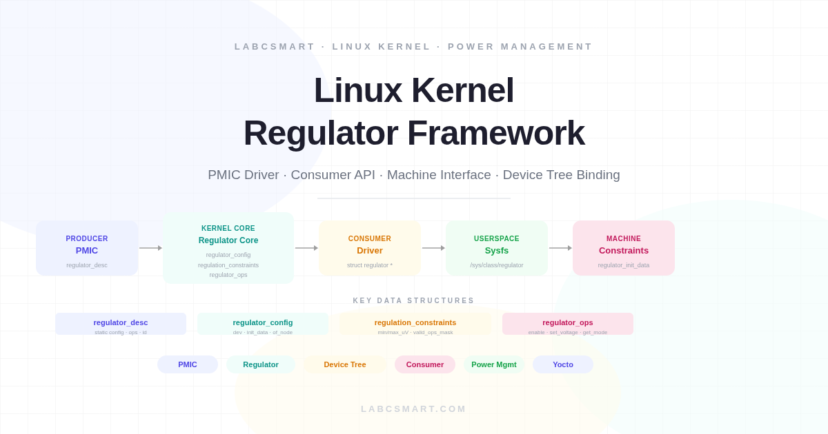
Figure 1 — The four interfaces of the regulator framework.
The producer interface is what a PMIC driver implements. It registers each regulator with the core by providing a static description (name, voltage range, register addresses) and a set of hardware-access callbacks (enable, disable, set voltage). The consumer interface is what device drivers use. A consumer calls devm_regulator_get(dev, "vmmc") to acquire a handle, then regulator_enable() to power on the rail. The machine interface provides constraints — voltage limits, always-on flags, allowed operations — sourced from the device tree. The sysfs interface exports every regulator at /sys/class/regulator/regulator.N/ for debugging.
The core sits in the middle and does the real work: it checks every consumer request against the constraints, manages reference counts (a shared rail stays enabled as long as at least one consumer needs it), resolves supply chains (regulators that power other regulators), and drives the sysfs interface.
Producer Data Structures
A PMIC driver describes each regulator with three structures. Understanding their relationship is essential.
Figure 2 — Producer data structures and their relationships.
The static description (regulator_desc) and the runtime config (regulator_config) are both passed to devm_regulator_register(). The core combines them with the constraints from the machine interface to create the internal regulator_dev. Let us look at each structure in detail.
regulator_desc — what the regulator is
This is const — one instance per regulator output, defined at compile time and never modified. It tells the core everything about the regulator’s hardware capabilities:
struct regulator_desc {
    const char *name;            /* logging + sysfs */
    const char *of_match;        /* DT child node name to match */
    const char *regulators_node; /* parent container, usually "regulators" */
    int id;
    unsigned n_voltages;         /* selector count; 1 = fixed output */
    const struct regulator_ops *ops;
    enum regulator_type type;    /* REGULATOR_VOLTAGE or _CURRENT */
    struct module *owner;
    unsigned int min_uV;         /* voltage at selector 0 */
    unsigned int uV_step;        /* per-selector increment */
    /* regmap integration: */
    unsigned int vsel_reg;       /* register holding voltage selector */
    unsigned int vsel_mask;      /* bit field within that register */
    unsigned int enable_reg;     /* register controlling enable/disable */
    unsigned int enable_mask;    /* bit(s) within that register */
    [...]
};
The vsel_reg/vsel_mask and enable_reg/enable_mask fields are the key to modern PMIC drivers. When filled in, you use the core’s regmap-based helpers — regulator_get_voltage_sel_regmap(), regulator_set_voltage_sel_regmap(), regulator_enable_regmap(), regulator_disable_regmap(), regulator_is_enabled_regmap() — instead of writing custom register access. This eliminates nearly all boilerplate from the driver.
When of_match is set (and regulators_node points to the container name, typically "regulators"), the core automatically walks the device tree at registration time, finds the matching child node, and extracts constraints. No manual DT walking required. This replaces the older of_regulator_match() approach, which required the driver to locate and parse DT nodes itself.
regulator_config — what the driver knows at probe time
This structure is built on the stack inside the probe function, once per regulator. It carries the runtime context that the core needs at registration time:
struct regulator_config {
    struct device *dev;
    const struct regulator_init_data *init_data;
    void *driver_data;
    struct device_node *of_node;
    struct regmap *regmap;
    struct gpio_desc *ena_gpiod;
};
Built on the stack in the probe function, once per regulator. The critical field is regmap: the PMIC’s regmap handle. Without it, the regmap helpers in the ops table won’t work. init_data is NULL if you let the core parse constraints from DT (the modern approach). Set it only if you need to provide constraints programmatically.
regulator_ops — how to talk to the hardware
For a linear regulator with regmap, the ops table looks like this:
static const struct regulator_ops my_buck_ops = {
    .list_voltage    = regulator_list_voltage_linear,
    .map_voltage     = regulator_map_voltage_linear,
    .get_voltage_sel = regulator_get_voltage_sel_regmap,
    .set_voltage_sel = regulator_set_voltage_sel_regmap,
    .enable          = regulator_enable_regmap,
    .disable         = regulator_disable_regmap,
    .is_enabled      = regulator_is_enabled_regmap,
};
Every callback here is a core-provided helper. The driver writes zero register access code. For fixed-output regulators (LDOs with a single voltage), you only need enable/disable/is_enabled and set n_voltages = 1.
For non-linear regulators (where voltage selectors don’t follow a fixed step), provide a volt_table array in the descriptor and use table-based helpers:
static const unsigned int ldo3_volt_table[] = {
    1500000, 1800000, 2500000, 2800000, 3000000, 3300000,
};

static const struct regulator_ops ldo3_ops = {
    .list_voltage    = regulator_list_voltage_table,
    .map_voltage     = regulator_map_voltage_iterate,
    .get_voltage_sel = regulator_get_voltage_sel_regmap,
    .set_voltage_sel = regulator_set_voltage_sel_regmap,
    .enable          = regulator_enable_regmap,
    .disable         = regulator_disable_regmap,
    .is_enabled      = regulator_is_enabled_regmap,
};
In the descriptor, set .volt_table = ldo3_volt_table and .n_voltages = ARRAY_SIZE(ldo3_volt_table). The core will iterate the table when mapping a requested voltage to the nearest selector.
Constraints and the Machine Interface
Constraints are the safety layer. They define what consumers are allowed to do. Every request passes through a constraint check before the core calls any hardware callback.
struct regulation_constraints {
    const char *name;
    int min_uV, max_uV;         /* allowed voltage window */
    int min_uA, max_uA;         /* allowed current window */
    unsigned int valid_ops_mask; /* what consumers may do */
    unsigned always_on:1;        /* never disable this rail */
    unsigned boot_on:1;          /* assume enabled at boot */
    struct regulator_state state_mem;  /* state during suspend-to-RAM */
    struct regulator_state state_disk; /* state during suspend-to-disk */
    [...]
};
If a consumer calls regulator_set_voltage(vcc, 5000000, 5000000) but the constraint says max_uV = 3300000, the core returns -EINVAL without touching the hardware. If the consumer calls regulator_enable() but valid_ops_mask doesn’t include REGULATOR_CHANGE_STATUS, the core returns -EPERM.
In device tree, constraints are standard properties on the regulator node: regulator-min-microvolt, regulator-max-microvolt, regulator-always-on, regulator-boot-on, regulator-ramp-delay. When regulator_desc.of_match is set, the core parses these automatically during devm_regulator_register(). No code needed in the driver.
The state_mem and state_disk fields control what happens to the regulator during system suspend. You can specify whether the rail should stay on, turn off, or switch to a specific voltage during suspend, using the DT sub-nodes regulator-state-mem and regulator-state-disk with properties like regulator-on-in-suspend, regulator-off-in-suspend, and regulator-suspend-microvolt.
Providing init_data programmatically (legacy and MFD)
In some cases, the driver cannot rely on the core’s automatic DT parsing — for instance when the PMIC is a sub-device inside a Multi-Function Device (MFD) and the parent driver passes constraints as platform data. In that case, the driver sets config.init_data explicitly:
static struct regulator_init_data my_init_data = {
    .constraints = {
        .name            = "BUCK1",
        .min_uV          = 850000,
        .max_uV          = 1600000,
        .valid_ops_mask  = REGULATOR_CHANGE_VOLTAGE
                         | REGULATOR_CHANGE_STATUS,
        .always_on       = true,
    },
};

/* In probe: */
config.init_data = &my_init_data;
config.of_node   = NULL; /* no DT parsing for this regulator */
When init_data is non-NULL, it takes precedence over DT parsing. This approach is also seen in older drivers that predate DT support or in MFD sub-drivers where the parent passes constraints through mfd_cell.platform_data.
The legacy of_regulator_match() approach
Before the core gained automatic DT matching (via regulator_desc.of_match), drivers had to walk the device tree manually using of_regulator_match(). This function takes a parent node, a match table, and populates each entry’s init_data and of_node fields:
static struct of_regulator_match my_matches[] = {
    { .name = "buck1" },
    { .name = "ldo1" },
};

/* In probe: */
parent = of_get_child_by_name(dev->of_node, "regulators");
ret = of_regulator_match(dev, parent, my_matches,
                         ARRAY_SIZE(my_matches));
of_node_put(parent);

/* Then use my_matches[i].init_data and my_matches[i].of_node
   when building regulator_config for each regulator */
This approach is still found in many in-tree drivers but is no longer necessary for new code. Setting of_match and regulators_node in the descriptor achieves the same result with less code and no manual DT walking.
Writing a PMIC Driver (Modern Approach)
Modern PMIC drivers (Linux 5.10+) are remarkably short because regmap and the core do most of the work. The probe function follows this pattern:
Figure 3 — Modern PMIC probe flow with regmap.
Each step in the loop builds a regulator_config on the stack, passes it alongside the corresponding regulator_desc to devm_regulator_register(), and the core takes care of DT parsing, constraint application, and sysfs creation. Let us now look at the device tree side.
Device tree binding
Each PMIC node in the device tree contains a regulators sub-node, and each child of that node represents one regulator output. The child node name must match the of_match field in the driver’s descriptor. Constraints are expressed as standard properties on each child node:
Figure 4 — DT structure: PMIC node, regulators container, individual outputs, and consumer binding.
Here is the corresponding device tree source for a PMIC with one variable-output buck and one fixed LDO:
my_pmic@48 {
    compatible = "vendor,my-pmic";
    reg = <0x48>;

    regulators {
        buck1 {
            regulator-name = "BUCK1";
            regulator-min-microvolt = <850000>;
            regulator-max-microvolt = <1600000>;
            regulator-ramp-delay = <12500>;
        };
        ldo1 {
            regulator-name = "LDO1";
            regulator-min-microvolt = <1100000>;
            regulator-max-microvolt = <1100000>;
            regulator-always-on;
            regulator-boot-on;
        };
    };
};
Notice that the container node is named regulators — this must match the regulators_node field in the descriptor. Each child node name (buck1, ldo1) must match the of_match field. The regulator-ramp-delay property tells the core how fast the regulator can slew, which is used to insert appropriate delays after voltage changes.
Driver code
Here is a complete, minimal PMIC driver for an I2C device with one buck regulator and one fixed LDO. The entire register access is handled by regmap helpers — the driver contains no manual read/write code:
#include <linux/i2c.h>
#include <linux/module.h>
#include <linux/regmap.h>
#include <linux/regulator/driver.h>

/* Register map (from PMIC datasheet) */
#define BUCK1_VSEL  0x10
#define BUCK1_CTRL  0x11
#define LDO1_CTRL   0x20

static const struct regmap_config my_pmic_regmap = {
    .reg_bits = 8,
    .val_bits = 8,
    .max_register = 0x3F,
};

static const struct regulator_ops buck_ops = {
    .list_voltage    = regulator_list_voltage_linear,
    .map_voltage     = regulator_map_voltage_linear,
    .get_voltage_sel = regulator_get_voltage_sel_regmap,
    .set_voltage_sel = regulator_set_voltage_sel_regmap,
    .enable          = regulator_enable_regmap,
    .disable         = regulator_disable_regmap,
    .is_enabled      = regulator_is_enabled_regmap,
};

static const struct regulator_ops ldo_fixed_ops = {
    .enable     = regulator_enable_regmap,
    .disable    = regulator_disable_regmap,
    .is_enabled = regulator_is_enabled_regmap,
};

static const struct regulator_desc my_regulators[] = {
    {
        .name            = "BUCK1",
        .of_match        = "buck1",      /* matches DT child node name */
        .regulators_node = "regulators", /* DT container node name */
        .id              = 0,
        .type            = REGULATOR_VOLTAGE,
        .owner           = THIS_MODULE,
        .n_voltages      = 16,
        .min_uV          = 850000,
        .uV_step         = 50000,
        .vsel_reg        = BUCK1_VSEL,
        .vsel_mask       = 0x0F,
        .enable_reg      = BUCK1_CTRL,
        .enable_mask     = BIT(7),
        .ops             = &buck_ops,
    },
    {
        .name            = "LDO1",
        .of_match        = "ldo1",
        .regulators_node = "regulators",
        .id              = 1,
        .type            = REGULATOR_VOLTAGE,
        .owner           = THIS_MODULE,
        .n_voltages      = 1,
        .min_uV          = 1100000,
        .enable_reg      = LDO1_CTRL,
        .enable_mask     = BIT(0),
        .ops             = &ldo_fixed_ops,
    },
};

static int my_pmic_probe(struct i2c_client *i2c)
{
    struct device *dev = &i2c->dev;
    struct regmap *regmap;
    int i;

    regmap = devm_regmap_init_i2c(i2c, &my_pmic_regmap);
    if (IS_ERR(regmap))
        return dev_err_probe(dev, PTR_ERR(regmap),
                             "regmap init failed\n");

    for (i = 0; i < ARRAY_SIZE(my_regulators); i++) {
        struct regulator_config config = {
            .dev    = dev,
            .regmap = regmap,
        };
        /* init_data = NULL: core parses constraints from DT
         * of_node: core resolves automatically via of_match
         */
        struct regulator_dev *rdev =
            devm_regulator_register(dev, &my_regulators[i], &config);
        if (IS_ERR(rdev))
            return dev_err_probe(dev, PTR_ERR(rdev),
                                 "register %s failed\n",
                                 my_regulators[i].name);
    }
    return 0;
}
That is the entire probe function. No manual DT walking, no of_regulator_match(), no custom register access. The of_match field in each descriptor tells the core which DT child node to parse for constraints. The regmap field in the config enables all the regmap helpers. devm_regulator_register() handles cleanup automatically.
Consumer API
Consumer drivers don’t care about PMIC internals. They request a regulator by supply name, and the core resolves it through the device tree:
Figure 5 — How the core resolves a supply name to a regulator handle.
When a consumer calls devm_regulator_get(dev, "vmmc"), the core appends "-supply" to get "vmmc-supply", finds that property in the consumer’s DT node, follows the phandle to the regulator node, and returns the corresponding struct regulator * handle. If the PMIC hasn’t probed yet, -EPROBE_DEFER is returned and the consumer’s probe is retried automatically.
Figure 6 — Consumer API lifecycle.
A typical consumer probe acquires one or more regulators, configures voltage if needed, and enables the rail before using the device:
struct regulator *vcc;

vcc = devm_regulator_get(dev, "vcc");
if (IS_ERR(vcc))
    return PTR_ERR(vcc);

/* Set voltage within the constraints defined in DT */
ret = regulator_set_voltage(vcc, 3300000, 3300000);
if (ret)
    return ret;

ret = regulator_enable(vcc);
if (ret)
    return ret;

/* device is powered — do work */

regulator_disable(vcc);
The DT binding on the consumer side is a single phandle property:
mmc0 {
    compatible = "vendor,sdhci";
    vmmc-supply = <&buck1>;
    vqmmc-supply = <&ldo1>;
};
The core appends "-supply" to the id string and searches the consumer’s DT node for that property. For instance, calling devm_regulator_get(dev, "vmmc") makes the core look for vmmc-supply in the consumer’s node, follow the phandle to the regulator, and return a handle to it.
Key consumer APIs
The following APIs cover the vast majority of consumer use cases. All have devm_ managed variants where applicable:
devm_regulator_get(dev, id): acquire a handle. If the supply is missing in DT, returns a dummy regulator (a no-op stub) so the consumer can work on boards without power management.- Use
devm_regulator_get_optional()if you need to distinguish “supply absent” from “supply present”.
- Use
regulator_enable()/regulator_disable(): reference-counted. The rail stays on until all consumers have disabled it.regulator_set_voltage(reg, min_uV, max_uV): the core picks the lowest voltage that satisfies all consumers on a shared rail. Checked against constraints.regulator_get_voltage(reg): reads the current output voltage in microvolts.regulator_set_load(reg, uA): declares load for DRMS (Dynamic Regulator Mode Switching). The core sums all consumer loads and tells the PMIC to switch between high-efficiency and high-performance modes.devm_regulator_bulk_get(dev, n, supplies): acquire multiple regulators in one call. Pairs withregulator_bulk_enable()/regulator_bulk_disable().
When a shared rail has multiple consumers calling regulator_set_voltage() with different ranges, the core resolves to the tightest overlapping window – the highest minimum and the lowest maximum. If the ranges don’t overlap, the call fails with -EINVAL.
The sysfs interface
Every registered regulator is exported at /sys/class/regulator/regulator.N/. Key attributes include name (the regulator name from the descriptor), type (voltage or current), microvolts (current output voltage), state (enabled or disabled), num_users (the reference count — how many consumers have enabled the rail), and min_microvolts / max_microvolts (the constraint window). This interface is read-only and provides a quick way to audit power rail states on a running system:
# ls /sys/class/regulator/regulator.0/
device  microvolts  min_microvolts  name  num_users
max_microvolts  state  suspend_mem_state  type

# cat /sys/class/regulator/regulator.0/name
BUCK1
# cat /sys/class/regulator/regulator.0/microvolts
1800000
# cat /sys/class/regulator/regulator.0/state
enabled
# cat /sys/class/regulator/regulator.0/num_users
2
The num_users attribute is particularly useful for debugging: if a rail is unexpectedly on, it tells you how many consumers still hold a reference. Tools like powertop parse these sysfs entries to build power consumption reports.
Summary
The regulator framework separates PMIC drivers from consumer drivers, with constraint enforcement as the safety layer between them. Modern PMIC drivers are short: fill in a regulator_desc array with regmap register addresses, provide a regmap handle in the config, and let the core handle DT parsing, constraint checking, and register access. Consumer drivers use a five-step lifecycle — get, enable, configure, use, release — with -EPROBE_DEFER handling probe ordering automatically.
If you need to write a PMIC driver, start by mapping the datasheet’s register layout to vsel_reg/vsel_mask/enable_reg/enable_mask fields. The core’s regmap helpers will do the rest.