For the needs of mass production of an industrial device built by one of our clients, LABCSMART was asked to set up a means of manufacturing requiring the least possible human intervention, in order to automate the production chain. These products of two different types were based on i.MX6 and i.MX8 respectively. We therefore had to go around the means made available by both the community and by NXP in order to achieve the desired objective. Added to our expertise, it was possible to set up the mechanisms that we describe in this blog post.
The choice finally fell on NXP’s UUU (Universal Update Utility) tool as well as a series of patches developed internally at LABCSMART. In order to present the context, Yocto was the build system used, and naturally, the mainline versions of U-boot and the Linux kernel were, although these had very little (if any) impact on the implemented mechanism.
Integration of the manufacturing tool
We will first integrate via a Yocto recipe the tool that will allow us to communicate with the i.MX SoCs when the latter are in Serial Download mode. This is UUU (Universal Update Utility), formerly mfgtools. Below is the recipe for compiling the tool statically. The idea is to be able to make it executable on any Linux system without having to install any dependencies first:
In the recipe above, the line EXTRA_OECMAKE = "-DSTATIC=ON"is responsible for the static compilation of UUU.
Now that we have the NXP dialog tool, we can attack the main element allowing to communicate with the tool in question, the bootloader.
Tweaking U-boot configuration
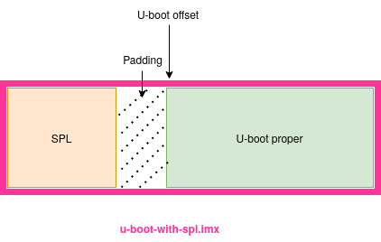
Although the sources for the SPL and u-boot are in the same place, the resulting binaries are separate. For the SPL, the binary has the same name. For u-boot, it is called u-boot proper. There are scenarios where these two binaries are concatenated to produce only one (this is our scenario). It should be noted that even in this case, the execution is done in two stages (SPL then u-boot proper) by connecting to their respective offsets.
The overall representation then looks like the diagram below
Now that we are familiar with the different components of the bootloader, we can move on to configuration.
Below are the configuration options (relating to the SPL) that need to be activated in the board configuration file:
The options enabled above will allow the SPL to support both USB in gadget and host mode, as well as support for SDP (Serial Download Protocol), which is the communication protocol used between the NXP SoCs and the UUU manufacturing tool.
The option CONFIG_SPL_USB_SDP_SUPPORT is quite particular. If enabled, the SPL code will detect if the board booted in recovery mode. The SPL code will then immediately enter in an infinite loop waiting for further downloads/commands over SDP from the host side, instead of branching (jumping) to u-boot proper’s start address.
Once these options have been activated, we will activate those relating to U-boot proper, which will allow us to support the different protocols necessary for manufacturing:
Below are some explanations:
CONFIG_CMD_FASTBOOT: enable support for U-boot’sfastbootcommand.CONFIG_USB_FUNCTION_FASTBOOTallows you to enable the USB part of the FASTBOOT protocol (inherited from the android world), allowing, among other things, to flash all or part of the storage mediasCONFIG_FASTBOOT_UUU_SUPPORTThis option enables FASTBOOT i.MX UUU special commands, which are “UCmd” command and “ACmd” command. These commands allow sending and running u-boot commands over the FASTBOOT protocolCONFIG_FASTBOOT_BUF_ADDR: any data to be processed must be downloaded into memory beforehand, and this option allows you to specify the address (in RAM) that will serve as a buffer. From U-boot’s environment, this value can be changed with viafastboot_buffervariable.CONFIG_FASTBOOT_FLASH: This option enables FASTBOOT protocol’s”flash” command (which includeswrite/erasesub-commands), which allows to write a downloaded image to a non-volatile storage device (such as the eMMC in our case) or simply to erase this storage device.CONFIG_FASTBOOT_FLASH_MMC_DEVspecifies the default MMC device for the fastboot “flash” command.CONFIG_FASTBOOT_MMC_BOOT_SUPPORTenables support for e.MMC boot partition 1 and 2 (erase/write)CONFIG_FASTBOOT_MMC_USER_SUPPORTenables eMMC userdata partition flash/erase (this is the main partition, of the order of several Gigabyte most of the time)CONFIG_FASTBOOT_MMC_USER_NAMEspecifies the name to be referred to via the fastboot protocol so that the latter knows that this is the user partition that we want to target. By default, this option is “emmc“. In our case, we set it to “foo_emmc” to highlight its use..CONFIG_FASTBOOT_MMC_BOOT1_NAMEandCONFIG_FASTBOOT_MMC_BOOT2_NAMEThe default target name for updating eMMC boot partition 1/2 (appearing on a Linux system as/dev/mmcblkXbootY). By default, these options aremmc0boot0andmmc0boot1respectively. We have changed them here to highlight their use in the UUU configuration script.CONFIG_CI_UDCallows to activate the driver of the USB controller integrated in the SoC (of whichChipIdeais the IP designer, hence the CI in the option name).CONFIG_USB_GADGETactivates support for USB gadget (OTG more precisely) over this USB controller. Note that when they start in serial download mode (thus via USB OTG), NXP’s i.MX chips are identifiable via a specific PID/VID pair, specific to NXP and also allowing the type of SoC to be identified. These IDs are recognized by UUU which can then easily communicate with the SoC. At the execution of the SPL, the USB gadget controller is reinitialized (thus emulating a new USB device). This is followed by a re-enumeration on the host side, and this is where the options below come into play:CONFIG_USB_GADGET_MANUFACTURER: Vendor name of the USB device emulated, reported to the host device. This is usually either the manufacturer of the device or the SoC, or any character string to identify the designer of the card.CONFIG_USB_GADGET_VENDOR_NUMetCONFIG_USB_GADGET_PRODUCT_NUM: These are respectively the Vendor ID and Product ID of the emulated USB device. These are usually the board or SoC vendor’s. That said, any manufacturer that has registered for a USB identifier pair (Vid/PID) can specify them in these fields. It will then be necessary to patch the UUU tool so that these IDs are recognized. By default, the0x0525/0xa4a5pair is recognized for i.MX type SoCs, hence its use in our configuration.
Once the configuration is complete, we can move on to the next step. In the past, it was common to produce two bootloader variants: one for manufacturing, allowing the board to be booted in a particular mode allowing factory manufacturing. This bootloader then had to flash a second bootloader, which was the production bootloader intended for normal use of the board. We will free ourselves from this mode because we will use the same bootloader in both factory and production environments. The idea is to make the bootloader smart enough to detect if the SoC boots in serial download mode, and in this case, it enters a particular mode waiting for commands/instructions.
i.MX6 related tweaks
In this section, we will modify the bootloader execution flow so that when it detects the system is booting in recovery mode, it immediately runs the fastboot command, and enters in a loop, waiting for further commands. To do that, we will apply the following patch on our board related C file in board/<vendor>/[<board_name>/]<board_name.>c (the exact path depends on the board provider):
In the above patch, the is_boot_from_usb() function (executed from u-boot proper) detects if the chip is in serial download (recovery) mode when booting. This behavior is already implemented in U-boot sources for i.MX type SoCs. Similar functions must certainly exist for other types of SoC. The rest of the patch is pretty self-explanatory. In case of booting in serial download mode, we execute the fastboot command which allows to put the chip on hold for FASTBOOT commands. These commands will be sent from the host, via UUU.
In order to automate the tasks of loading, flashing and configuration, UUU gives the possibility of going through a script, which it will parse and process in a linear fashion, executing the commands one after the other. For our i.MX6 SoC, this has the form below:
Earlier in this post we talked about scenarios where the SPL and u-boot proper were concatenated to produce a single binary. This is the case here, hence the name u-boot-with-spl.imx. Via the script, the binary is therefore loaded into memory and executed. Then, following the reset, we inform UUU of the new identifiers through which it will have to access our device.
The u-boot-with-spl.imx which contains the u-boot image at some offset, and u-boot is expected to be located in RAM at a particular address (that is, the address passed as the load address with mkimage). Thus, we need to obtain u-boot’s load address and u-boot’s offset in u-boot-with-spl.imx.
Obtaining the load address is quite simple. Either from U-boot’s Yocto temp directory as the following:
or the following:
To obtain the u-boot offset from within the u-boob-with-spl.imx file, we will use hexdump to look for U-boot’s magic number. This magic number is defined in include/image.h in u-boot sources as the following:
with hexdump -C, it would result in 27 05 19 56. Let’s first look for this magic number in u-boot.img and extract the corresponding row that will be used as pattern in the concatenated U-boot binary:
We can see that we have this magic number at offset 0x00000000. Let’s now use the whole 27 05 19 56 ac 19 b5 65 pattern in the concatenated u-boot binary:
In the previous snippet, we can see that u-boot proper’s offset in u-boot-with-spl.imx is 0x11000. Back to the manufacturing, u-boot image is expected to be loaded to 0x17800000. Note the image has a 64-byte header, so the real address to load the image at is 0x17800000 - 64 = 0x177fffc0. Then combined with the offset from within u-boot-with-spl.imx, to have the U-Boot image located at 0x177fffc0, u-boot-with-spl.imx should be loaded at 0x177fffc0 - 0x11000 = 0x177eefc0. Hence the following lines in the script:
The first one loads the concatenated binaries, and the second one jumps to the address where u-boot executable is expected.
On a physical storage device (eMMC or SD card for example), the i.MX6 boot rom expects the SPL to be at offset 0x400 (1KB). The offset 0x00011000 we have just found using hexdump is actually 68KB. This is the reason why, when flashing separated SPL and U-boot proper binaries using dd using bs=1K for example, for the SPL, we use seek=1, and for U-boot, we use seek=69, which is 69KB from the beginning of the storage device, but 68KB from the offset of the SPL.
Still in the script, we set the address of the fastboot buffer to 0x12c00000 (identical to ${loadaddr} used most of the time for i.MX6 type Socs). Although this address can be specified from the configuration file, it can easily be changed from the U-boot environment. Since we will use the same configuration for the i.MX8, we will modify this address during production.
FB:this prefix is for fastboot command, and “FB: ucmd” is to send and execute u-boot commands via the FASTBOOT protocol.FB: download -f u-boot-with-spl.imxis used to loadu-boot-with-spl.imxin the fastboot buffer.FB: ucmd mmc dev 3 1selects the first hardware partition (boot0) on mmc device 3 (which is our eMMC)FB: ucmd mmc erase 0 0x4000erases the selected partitionFB: ucmd mmc write \${fastboot_buffer} 0x2 0x${UBOOT_HEX_SIZE_IN_SECTORS}writes the content of${fastboot_buffer}(which is a U-boot env var) to the selected device, at offset0x2in term number of sectors, with a sector size being of512B. It then corresponds to 1KB.${UBOOT_HEX_SIZE_IN_SECTORS}is the size of the content to write, and it is a Yocto variable (which means it will be replaced by its real value when the script is generated) representing the size ofu-boot-with-spl.imxin terms of number of sectors. We could have usedFB: flash foo_mmc0boot0 u-boot-with-spl.imxandFB: flash foo_mmc0boot1 u-boot-with-spl.imxbut the fastboot’s ‘flash‘ command does not support offset on the target device. Using it would result in flashing from offset0x00, while the i.MX6 boot ROM expects the boot code at offset0x400(1KB)FB: ucmd mmc partconf 3 1 1 0marks the 1rst hardware partition of the mmc#3 as bootable.FB: flash -raw2sparse foo_emmc mmc.imgwill flashmmc.imgto the partition namedfoo_emmc, which corresponds to what we have specified while configuring U-boot.mmc.imgcorresponds the the resulting wic image that has simply been renamed.FB: ucmd fuse prog -y 0 5 0x1860andFB: ucmd fuse prog -y 0 6 0x10in this case are used to program the fuses so the device boot from fuse, on usdhc4, which is where our eMMC is connected. You should not use these values or at least you must make sure these correspond to your use case.
Now that we have had some explanations of all of the lines in our UUU script, we can put everything in a Yocto class that will automatically generate it along with the size parameters that need to be set at build time.
Put everything together
Everything put together, we can imagine a Yocto class that is inherited by each image that need to be used in the manufacturing:
The previous class snippet, in the do_generate_uuu_configuration() function, we compute the bootloader binary size in hex, since U-boot’s mmc write command does only accept the size parameter in hexadecimal, and in term of number of sectors. After that, the function generate a suitable configuration. The do_manufacturing_bundle() function creates a manufacturing directory that contains the static-compiled version of UUU so it can be portable, as well as a bundle (a zip compressed archive actually) that will contain both uuu.auto, the bootloader binary (that is, u-boot-wit-spl.imx) and mmc.img. To start the flashing, you just have to boot your board in recovery mode and then sudo ./uuu <foo>_manufacturing_bundle.zip. UUU will automatically detect the file format and locate uuu.auto.
Now we are ready to boot our device and see what it prints in output:
In the previous snippet, we have an error. This error is from the SPL, and it means that the boot rom could load and execute the SPL, but the SPL was not able to find a suitable device from where it should load the bootloader. The SPL looks for that device in the function spl_boot_device(), which should return the list of devices from where the bootloader can be loaded. In the case of i.MX6, the function always returns BOOT_DEVICE_MMC1, which does not correspond to the eMMC interface but instead, SD-related. To fix the issue, the following patch has been added to the bootloader recipe (in Yocto):
In the previous patch, we have changed the MMC interface that has to be returned when the device is requested to boot from the eMMC. After this patch has been applied and everything rebuilt, we can reboot the device in recovery mode and restart the manufacturing using sudo uuu manufacturing_dundle.zip. Once done, we have the following output:
In the previous logs, we can see that the MMC interface from where the SPL tried to load U-boot proper changed from MMC1 to MMC2 and that it successfully loaded it. We also see U-boot normal boot logs, with the default default 3s counter.
All that being done, our manufacturing system is ready for production. We can commit everything and ship it for testing. After having implemented everything for the i.MX6, we can do the same for the i.MX8, as in the next section.
i.MX8 related tweaks
While the bootloader’s configuration can remain the same for both SoC, we will have some differences in UUU script, which would look as the following in case of i.MX8 (it also depends on which variant of i.MX8 you have; in this case, it is imx8qxp):
In the previous script, we have first changed the FASTBOOT buffer address so it corresponds to our i.MX8-related U-boot env’s load address, because in our default configuration it was 0x12C00000, which is an i.MX6-related configuration value. Thus, in the previous snipped, instead of the line FB: ucmd setenv fastboot_buffer ${loadaddr}, we could have just defined CONFIG_FASTBOOT_BUF_ADDR=0x42800000 in our i.MX8 board configuration file.
Moreover, we did not need to flash the boot partitions because the bard has an SPI NOR flash that is use to store the bootloader, and the configuration switches on the board was set to always boot from this SPI NOR. For the rest of the code (i.e the implementation on the function do_manufacturing_bundle()), it has to be adapter to put whatever is need to boot/flash the device into ${MFG_DIR}/${BUNDLE_NAME} before the bundle is created with zip.
Conclusion
In this blog post we have learnt how to implement the software part of the factory flashing on an embedded Linux system with U-boot as the bootloader, designed with two NXP chips which are the i.MX6 and i.MX8. We have seen how to configure and how to tweak the bootloader. We Could have also used the UMS (USB Mass Storage gadget) for this, but it would have been necessary to manually switch between the eMMC hardware partitions. The mechanism described in this post can easily be adapted to other SoCs (from different vendors), provided that you have the host tools to make it automatic. And you what method do you use? post in comments.