
A PC and an industrial x86 board boot the same way: firmware first, then a boot loader, then the kernel. What sits in each of these stages has changed a lot since the IBM PC, and an embedded x86 product touches all of them: the UEFI firmware and its variables, the CPU microcode, the ACPI tables that describe the board, and the boot loader or Unified Kernel Image that starts Linux. This article follows that chain from power-on to the kernel.
We have followed this path before on this blog for 64-bit Arm, in The arm64 Boot Flow, from the Boot ROM through SPL, TF-A, OP-TEE and U-Boot to Linux. On x86, the Boot ROM, SPL and U-Boot give way to the UEFI firmware, and the device tree to ACPI.
Contents
The Boot Chain
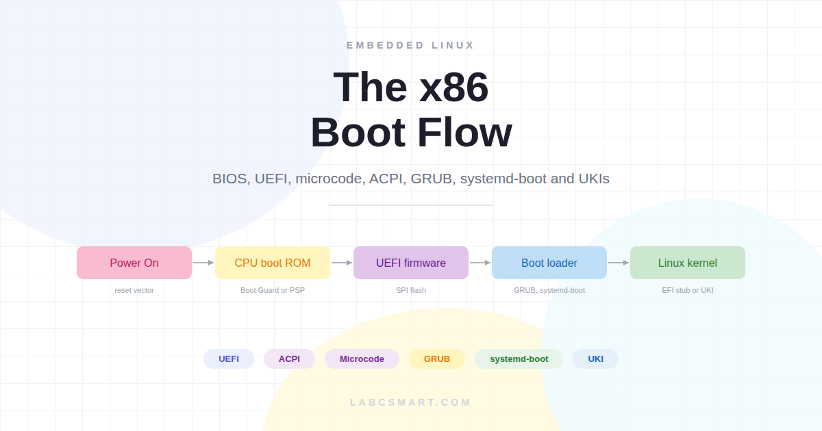
Each stage of the boot hands control to the next one, and each one is a little more capable than the previous: the firmware brings up the platform, the boot loader finds and loads the kernel, and the kernel takes over the hardware and starts user space.

On a modern x86 machine, something even runs before the firmware. Intel processors with Boot Guard first run an Authenticated Code Module, signed by Intel and stored in the firmware flash, which the processor verifies before running it; the module then checks the first block of the firmware. AMD processors start a dedicated Arm core, the Platform Security Processor, from its own ROM, and release the x86 cores only afterwards. The code built into the processor, which checks the ACM on Intel, and the PSP ROM on AMD, are the actual root of trust, the counterpart of the Boot ROM of an Arm SoC; the UEFI firmware itself lives in SPI flash and gets updated over the life of the product.
From BIOS to UEFI
The legacy BIOS ruled x86 machines from the IBM PC of 1981 until the early 2010s. UEFI was specified in the mid-2000s and became the norm on PCs around 2011 and 2012, when Windows 8 required it for new machines. Today, practically every x86 board ships with UEFI firmware, often with a legacy BIOS compatibility mode (CSM) that recent platforms have dropped.

The BIOS runs in 16-bit real mode and can address 1 MB of memory. Its disk format, the MBR, limits disks to 2 TB and four primary partitions. UEFI hands over to its applications in 32-bit or 64-bit mode, uses GPT disks, loads boot loaders from a file system, and brings Secure Boot and measured boot.
Legacy BIOS
New designs no longer use the BIOS, but its limits shaped the boot loaders still in use today, and some industrial boards still offer a legacy mode. Its boot sequence is short.
BIOS, the original firmware
The Basic Input/Output System lives in a flash chip on the motherboard, separate from the disks, which is why its setup screen is reachable with no disk attached. It runs in 16-bit real mode, and offers its services to the operating system through software interrupts, a design that dates back to the IBM PC.
At power-on, the BIOS runs its Power-On Self-Test, during which it initializes memory and checks the main components. It then looks for a bootable device in the configured order, and loads the first sector of the selected disk at address 0x7C00.
The Master Boot Record
That first sector is the Master Boot Record, exactly 512 bytes long.

It holds 446 bytes of bootstrap code, a partition table of four 16-byte entries, and a 2-byte signature, the bytes 0x55 then 0xAA, for the BIOS to treat the sector as bootable. Its partition entries use 32-bit sector addresses, so with 512-byte sectors a disk cannot exceed 2 TB, and the table has room for four primary partitions, or three and an extended one. These limits led to GPT, the GUID Partition Table, defined along with UEFI.
Why BIOS boot loaders come in stages
446 bytes cannot hold file system drivers, so a BIOS boot loader is split in stages, each one loading a larger next one.
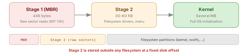
Stage 1, in the MBR, only reads raw sectors through the BIOS disk service, INT 13h. It loads stage 2 from a fixed place, usually the gap between the MBR and the first partition, where no file system is needed to find it. Stage 2 is the real boot loader: file system drivers, a configuration file, a menu, and the code that loads the kernel and follows its boot protocol. GRUB still has this structure on BIOS machines, with boot.img in the MBR and core.img right after it.
UEFI
UEFI replaced the BIOS with a firmware that loads files rather than disk sectors, keeps its settings in variables that Linux can change, and checks signatures before running anything.
A different model
UEFI keeps nothing of the BIOS interface. The firmware itself still starts in real mode at the reset vector, as every x86 processor does, but switches to protected or long mode early, and everything it starts afterwards runs in 32-bit or 64-bit mode. It has a modular driver model, a network stack for PXE and HTTP boot, and the Graphics Output Protocol in place of the VGA BIOS.

Some UEFI services stay available after the operating system has started: the runtime services. Linux uses them to read and write UEFI variables, which is how the boot configuration can be changed from the running system. Implementations differ between vendors, but all follow the UEFI specification, so the same operating system image boots on any compliant firmware.
The EFI System Partition
Instead of raw sectors, UEFI loads its applications from a file system, on the EFI System Partition (ESP).

The ESP is a FAT partition, FAT32 in practice. On a GPT disk it is identified by the partition type GUID C12A7328-F81F-11D2-BA4B-00A0C93EC93B, and on an MBR disk by the type 0xEF. Its size depends on what it holds: a few tens of megabytes for a boot loader alone, several hundred when it also stores kernels or Unified Kernel Images. Several operating systems can share one ESP, each in its own directory. Linux mounts it on /boot/efi, or /efi on recent systemd-based systems.
Files on the ESP
Everything lives under /EFI/. The /EFI/BOOT/ directory holds the default boot loader, the one the firmware runs when no boot entry is configured: first boot, removable media, or a reset of the firmware settings.
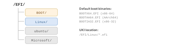
The default file name depends on the architecture:
# Default EFI binaries, in /EFI/BOOT/
BOOTX64.EFI   x86-64
BOOTIA32.EFI  32-bit x86
BOOTAA64.EFI  64-bit Arm (AArch64)
BOOTARM.EFI   32-bit Arm
With Secure Boot off, the firmware does not care what that binary is, as long as it is a valid PE/COFF executable for its architecture: GRUB, systemd-boot, shim, or a Unified Kernel Image all work. Operating systems install their own files in vendor directories, such as /EFI/ubuntu/ or /EFI/Microsoft/Boot/, and register them as boot entries.
# tree /boot/efi on a machine with Ubuntu, a UKI and Windows
/boot/efi/
|-- EFI/
|   |-- BOOT/
|   |   |-- BOOTX64.EFI          # default: usually shim or GRUB
|   |   |-- fbx64.efi            # fallback manager
|   |-- ubuntu/
|   |   |-- shimx64.efi          # Secure Boot shim
|   |   |-- grubx64.efi          # GRUB, verified by shim
|   |   |-- grub.cfg
|   |-- Linux/
|   |   |-- linux-6.6.0.efi      # Unified Kernel Image
|   |-- Microsoft/
|       |-- Boot/
|           |-- bootmgfw.efi     # Windows Boot Manager
|-- loader/
    |-- loader.conf              # systemd-boot configuration
    |-- entries/
        |-- linux.conf
The ESP is FAT, with no permissions: anything able to write to it can replace a boot binary. Secure Boot limits what such a change can do, since the firmware refuses to run a binary whose signature it does not trust; unsigned files on the ESP, such as grub.cfg or a separate initrd, stay unprotected.
How the firmware picks what to boot
The firmware reads its boot entries from UEFI variables. Each entry names a disk, a partition and the path of an EFI application. The firmware tries the entries in the order given by BootOrder, and runs the first one it can load. When none works, or none exists, it looks for \EFI\BOOT\BOOTX64.EFI on the available devices, which is how a USB stick boots with no prior setup.
“The first one it can load” matters: the firmware moves to the next entry only when an application is missing, invalid, refused by Secure Boot, or returns to the firmware with an error. Once the kernel has taken over, the firmware is out of the loop, and a kernel that crashes later does not make it try the next entry.
CPU Microcode
Before the kernel does any real work, the processor itself may need fixing. That is the job of microcode updates, which travel with the firmware, the initrd, or both.
Microcode and its updates
x86 processors decode complex instructions into simpler internal operations, driven by microcode stored in the processor. Intel and AMD publish microcode updates that fix hardware errata and security issues, such as Spectre or Downfall. An update is held only in volatile memory inside the processor: it must be applied again at every reset, on every core, and the processor signature (family, model and stepping) decides which update applies.
Three moments to load it
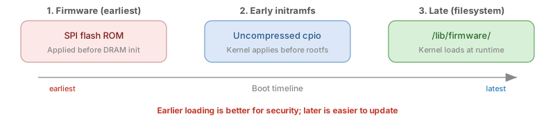
- By the firmware. Intel firmware carries microcode in its flash, indexed by the Firmware Interface Table, and the processor applies it before the firmware runs. It is the earliest option, but updating it means reflashing the firmware.
- From the early initramfs. An uncompressed cpio archive placed in front of the initramfs carries the microcode, and the kernel applies it at the very start of its boot. This is what Linux distributions do: early enough, and updated like any package.
- Late, from
/lib/firmware. The kernel can load an update on a running system. Changing microcode under running code is risky; recent kernels disable it by default (CONFIG_MICROCODE_LATE_LOADING) and mark the kernel as tainted when it is used.
Where the kernel finds it
For early loading, the cpio archive holds a single file, kernel/x86/microcode/GenuineIntel.bin or AuthenticAMD.bin, which bundles the updates for many processors. iucode_tool --write-earlyfw builds it for Intel; for AMD, the files of linux-firmware are used as they are. The kernel picks the entry matching its processor.
Late loading reads files named after the processor: one per family, model and stepping on Intel, one per family on AMD:
# Intel: one file per family-model-stepping (hexadecimal)
ls /lib/firmware/intel-ucode/
# 06-8c-01  06-8c-02  06-8e-09  06-9e-0d  06-b7-01 ...

# AMD: one file per family
ls /lib/firmware/amd-ucode/
# microcode_amd.bin  microcode_amd_fam17h.bin  microcode_amd_fam19h.bin

# Late reload (only with CONFIG_MICROCODE_LATE_LOADING=y)
echo 1 > /sys/devices/system/cpu/microcode/reload
A processor with family 6, model 0x8c and stepping 1 makes the kernel open 06-8c-01 directly. The last line asks it to look for a newer file and apply it; without late loading support, that reload file does not exist.
Several archives in one initrd
The kernel accepts an initrd made of several cpio archives one after the other. That is how microcode, and optionally ACPI table overrides, travel with the initramfs.

The early archives must come first and stay uncompressed; the kernel recognizes each one by its 070701 newc header. The initramfs that follows can be compressed. The boot loader passes the whole file without looking inside, so this works the same with GRUB, systemd-boot or a UKI. On the portable imaging instrument described in the ACPI section, the production UKIs carry exactly these two early archives, microcode and ACPI tables, and no initramfs at all: the kernel mounts the root file system by itself.
Microcode in boot loader configurations
Each boot loader lists the archives in its own syntax, microcode first. systemd-boot, GRUB and UKIs are described further down:
# systemd-boot: one initrd line per archive, in order
# /loader/entries/linux.conf
title   Linux
linux   /vmlinuz-linux
initrd  /intel-ucode.img
initrd  /initramfs-linux.img
options root=UUID=0a3407de-014b-458b-b5c1-848e92a327a3 rw quiet

# GRUB: several files on one initrd line
menuentry 'Linux' {
    linux   /boot/vmlinuz root=UUID=0a3407de-014b-458b-b5c1-848e92a327a3 rw quiet
    initrd  /boot/intel-ucode.img /boot/initramfs.img
}

# UKI: the first --initrd is the microcode
ukify build --linux=/boot/vmlinuz \
    --initrd=/boot/intel-ucode.img --initrd=/boot/initramfs.img \
    --output=linux.efi
Whatever the syntax, the order is the same in all three: the microcode archive first, then the initramfs.
Checking what was applied
The running revision is in /proc/cpuinfo, and the kernel log tells whether the early update was applied:
# Revision running now
grep -m1 microcode /proc/cpuinfo
# microcode       : 0x2b000603

# Early loading leaves a trace at the very start of the boot
dmesg | grep microcode
# [    0.000000] microcode: updated early: 0x2b000571 -> 0x2b000603, date = 2024-02-29
If the revision is older than the latest one published for that processor, the microcode archive is probably missing from the initrd, or placed after the initramfs.
ACPI Tables
Where an Arm board hands a device tree to the kernel, an x86 board hands it ACPI tables, built by the firmware. They describe the hardware that cannot be discovered, and they can be fixed from Linux when the firmware gets them wrong.
Describing the platform
Many parts of a board cannot be discovered by enumeration the way PCI devices can: GPIO controllers, thermal zones, interrupt routing, power management. On x86, the firmware describes them in ACPI tables, the Advanced Configuration and Power Interface.

ACPI also drives power management: sleep states from S0 to S5, processor performance and idle states, thermal zones. Every x86 PC and server relies on it. On Arm, the device tree is the norm for embedded systems, and ACPI is used by servers and SystemReady-certified machines.
The table hierarchy
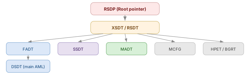
The entry point is the RSDP, the Root System Description Pointer. On UEFI, the firmware gives its address in the EFI system table; on a legacy BIOS, the kernel finds it by scanning the Extended BIOS Data Area and the 0xE0000 to 0xFFFFF range for its RSD PTR signature. The RSDP points to the XSDT, which lists all other tables: the FADT, which points to the DSDT with the main device descriptions; SSDTs, which add devices; the MADT, which describes interrupt controllers and processors; the MCFG, with the PCIe configuration space addresses.
ACPI and the device tree
The main difference with a device tree is that ACPI tables contain code. Their methods, in AML bytecode, run in the kernel’s AML interpreter and can read and write hardware. That makes ACPI more capable, for power management in particular, and harder to get right.

Linux supports both. x86 uses ACPI; embedded Arm and RISC-V boards use device trees; Arm servers and, increasingly, RISC-V servers use ACPI.
ACPI during the boot
The firmware places the tables in reserved memory before starting the boot loader. The kernel reads them early, matches the devices they describe to drivers through their _HID identifiers, and keeps running their methods for power states, frequency scaling and thermal management.
Reading the tables
The kernel exposes the raw tables in sysfs, and acpidump can extract them one by one. Both give the binary tables, AML for the DSDT and SSDTs and fixed data structures for the others, which iasl turns back into source:
# Tables present
ls /sys/firmware/acpi/tables/
# APIC  BGRT  DSDT  FACP  FACS  HPET  MCFG  SSDT  XSDT ...

# Decompile the DSDT into ASL source
sudo cat /sys/firmware/acpi/tables/DSDT > dsdt.dat
iasl -d dsdt.dat            # writes dsdt.dsl

# Dump and decompile one table, here the MADT
sudo acpidump -b -t APIC    # writes apic.dat
iasl -d apic.dat
iasl, from the acpica-tools package, converts between the binary AML of the firmware and ASL source. It is also the tool to write table overrides.
Fixing the firmware’s tables
Firmware tables have bugs: a wrong GPIO number, a missing device, a broken thermal zone. When the vendor does not fix them, or when reflashing the firmware of a fielded product is not an option, Linux can replace tables or add new ones at boot, with CONFIG_ACPI_TABLE_UPGRADE=y, as long as kernel lockdown is not active.
An SSDT can add a device without replacing the whole DSDT. On a portable imaging instrument we worked on, a QSPI NOR flash wired to one of the SPI controllers of the x86 module holds data that Linux has to update in the field, and the vendor firmware did not describe it at all. This SSDT adds it under its SPI controller:
// qspi-flash.asl
DefinitionBlock ("", "SSDT", 2, "CUSTOM", "QSPIFLSH", 0x00001000)
{
    External (\_SB_.PC00.SPI2, DeviceObj)

    Scope (\_SB.PC00.SPI2)
    {
        Device (QSPI)
        {
            Name (_HID, "PRP0001")
            Name (_DDN, "QSPI NOR flash, 512 Mbit")
            Name (_CRS, ResourceTemplate () {
                SpiSerialBusV2 (
                    1,                      // chip select 1
                    PolarityLow,            // chip select active low
                    FourWireMode,
                    8,                      // 8-bit words
                    ControllerInitiated,
                    33000000,               // 33 MHz
                    ClockPolarityLow,       // SPI mode 0
                    ClockPhaseFirst,
                    "\\_SB.PC00.SPI2",     // SPI host controller
                    0)
            })
            Name (_DSD, Package () {
                ToUUID ("daffd814-6eba-4d8c-8a91-bc9bbf4aa301"),
                Package () {
                    Package () { "compatible", Package () { "jedec,spi-nor" } }
                }
            })
        }
    }
}
External declares the SPI controller, which the firmware’s DSDT defines; _CRS describes how the flash hangs off it: chip select, SPI mode and clock rate. The interesting part is the identifier. PRP0001 tells Linux to match the device by the compatible property found in _DSD, exactly as it would in a device tree, so the generic spi-nor driver binds to it and the flash shows up as an MTD device, with no driver change.
Not every conflict calls for a new table. On a platform of industrial PCs we built, the hardware monitoring chip, an ITE IT87 Super I/O, is also claimed by the firmware’s ACPI tables, and its Linux driver refuses to load when ACPI already owns its I/O ports. The driver has an option for exactly that case, so the kernel command line of those machines carries it87.ignore_resource_conflict=1.
The compiled table goes into an uncompressed cpio archive, under kernel/firmware/acpi/, placed at the front of the initrd:
iasl qspi-flash.asl                      # writes qspi-flash.aml
mkdir -p kernel/firmware/acpi
cp qspi-flash.aml kernel/firmware/acpi/
find kernel | cpio -o -H newc > acpi-override.cpio   # not compressed

# Microcode, ACPI overrides, then the initramfs
cat microcode.cpio acpi-override.cpio initramfs.cpio.gz > initrd.img
A new SSDT is added to the firmware’s tables; a table with the same signature and identifiers as a firmware one, such as a corrected DSDT, replaces it. During development, a table can also be loaded on a running system through configfs, with CONFIG_ACPI_CONFIGFS=y:
mkdir /sys/kernel/config/acpi/table/qspi
cat qspi-flash.aml > /sys/kernel/config/acpi/table/qspi/aml
Writing the AML file into the aml attribute loads the table at once, and removing the directory unloads it, which makes it easy to try successive versions of a table before packing the final one into the initrd.
The Linux EFI Stub
UEFI only runs PE/COFF executables, and a Linux kernel is not one by default. With CONFIG_EFI_STUB=y, available since Linux 3.3, the kernel image carries a PE/COFF header and a small EFI application, and the firmware can start it directly.
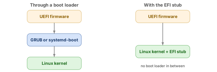
That is the shortest possible chain, but it comes without a menu or a way to choose a kernel, and the command line has to be stored in the boot entry or built into the kernel. systemd-boot can only start a kernel built with the EFI stub, and GRUB starts such kernels too, so enabling it costs nothing.
# Kernel and initrd on the ESP
cp /boot/vmlinuz-6.6.0    /boot/efi/EFI/Linux/vmlinuz-6.6.0.efi
cp /boot/initrd.img-6.6.0 /boot/efi/EFI/Linux/initrd-6.6.0.img

# Boot entry that starts the kernel itself, with its command line
efibootmgr --create --disk /dev/sda --part 1 --label "Linux 6.6.0" \
    --loader '\EFI\Linux\vmlinuz-6.6.0.efi' \
    --unicode 'root=PARTUUID=4f9b6c1e-02 rw quiet initrd=\EFI\Linux\initrd-6.6.0.img'
The stub reads the initrd= path, written with backslashes, from the partition it was itself loaded from, the ESP here. Some firmware implementations handle long command lines in boot entries badly; a UKI, which carries its own command line, avoids the problem.
EFI Variables
UEFI variables live in the firmware’s non-volatile storage, usually the same SPI flash as the firmware. They survive power cycles and reinstallations, are readable from the firmware setup and from Linux, and are grouped in GUID namespaces.
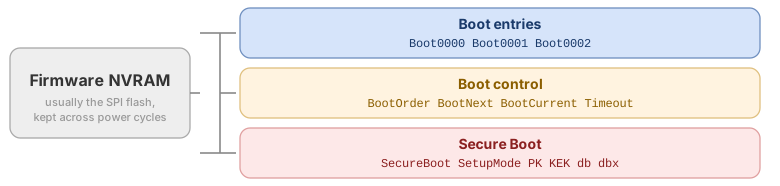
BootOrder: the boot entries to try, in order, such as0000,0003,0001.Boot0000toBootFFFF: the entries themselves, each with a device path, a file path and optional data.BootCurrent: the entry used for the current boot.BootNext: an entry to use for the next boot only. The firmware deletes it as it boots, which makes it the basis of a “try once” update.Timeout: how long the firmware boot menu waits.
Linux exposes them in /sys/firmware/efi/efivars/, and efibootmgr manages the boot entries:
# Entries, order and current boot, with device paths
efibootmgr -v

# One variable, raw
hexdump -C /sys/firmware/efi/efivars/BootOrder-8be4df61-93ca-11d2-aa0d-00e098032b8c

# New entry for a boot loader on partition 1
efibootmgr --create --disk /dev/sda --part 1 \
    --label "Linux" --loader '\EFI\BOOT\BOOTX64.EFI'

# Change the order, disable or delete an entry
efibootmgr --bootorder 0003,0001,0000
efibootmgr --bootnum 0001 --inactive
efibootmgr --bootnum 0002 --delete-bootnum

# Boot entry 0004 once, for the next boot only
efibootmgr --bootnext 0004
BootNext is what makes UEFI usable for A/B updates: the new system boots once, and only becomes the default if it proves healthy. Our article on x86 Secure Boot and A/B updates with Yocto and RAUC shows how two production systems build A/B updates on it.
Boot Loaders on UEFI
On UEFI, a Linux system can be started in three ways, from the simplest to the most capable.

- Direct boot of an EFI stub kernel or a UKI: nothing between the firmware and Linux. It suits fixed embedded configurations.
- systemd-boot: a small menu driven by text files on the ESP, which loads EFI binaries only from the ESP or an extended boot partition.
- GRUB: file system drivers, network boot, encrypted disks and a scripting language.
systemd-boot
systemd-boot reads a global loader.conf and one file per boot entry, all on the ESP. This configuration offers a normal entry and a recovery one, each with the microcode archive first:
# /loader/loader.conf
default  linux-lts.conf
timeout  3
editor   no                 # no command line edits at the boot menu

# /loader/entries/linux-lts.conf
title   Linux LTS
linux   /vmlinuz-linux-lts
initrd  /intel-ucode.img
initrd  /initramfs-linux-lts.img
options root=UUID=0a3407de-014b-458b-b5c1-848e92a327a3 rw quiet

# /loader/entries/recovery.conf
title   Recovery
linux   /vmlinuz-linux-lts
initrd  /intel-ucode.img
initrd  /initramfs-linux-lts-fallback.img
options root=UUID=0a3407de-014b-458b-b5c1-848e92a327a3 rw single
systemd-boot reads its files from the ESP, or from an extended boot partition (XBOOTLDR); kernels on the root file system are out of its reach. It also finds UKIs in /EFI/Linux/ by itself, without entry files. editor no matters on a product: otherwise, anyone at the console can add init=/bin/sh to the command line. systemd-boot can also count boot attempts, by renaming entry files, and fall back to another entry when one keeps failing.
GRUB
GRUB reads grub.cfg. This one loads the modules it needs to read a GPT disk and an ext4 partition, finds the root partition by its UUID, and declares two entries:
# grub.cfg
set timeout=5
set default=0

insmod part_gpt
insmod ext2
search --no-floppy --fs-uuid --set=root 0a3407de-014b-458b-b5c1-848e92a327a3

menuentry 'Linux' --class linux {
    linux   /boot/vmlinuz root=UUID=0a3407de-014b-458b-b5c1-848e92a327a3 rw quiet
    initrd  /boot/initramfs.img
}

menuentry 'Linux (fallback)' --class linux {
    linux   /boot/vmlinuz.old root=UUID=0a3407de-014b-458b-b5c1-848e92a327a3 rw single
    initrd  /boot/initramfs.old.img
}
GRUB keeps a small environment block, grubenv, that its scripts can read and write. That is enough to count boot attempts and fall back after three failures. GRUB has no arithmetic, so the counter moves from one value to the next by hand, and user space clears it once the system is up:
# grub.cfg: count attempts, fall back after three
load_env
if   [ "${boot_count}" = "" ];  then set boot_count=1
elif [ "${boot_count}" = "1" ]; then set boot_count=2
elif [ "${boot_count}" = "2" ]; then set boot_count=3
else set default=1               # the fallback entry
fi
save_env boot_count

# In user space, once the system is healthy
grub-editenv /boot/efi/EFI/BOOT/grubenv unset boot_count
GRUB’s scripting language is not a shell: there is no command substitution or sed, but regexp extracts parts of a string. This loop makes one entry per installed kernel; extra arguments of menuentry reach its body as $2, $3 and so on:
for kernel in /boot/vmlinuz-*; do
    regexp --set=1:version '^/boot/vmlinuz-(.*)$' "$kernel"
    menuentry "Linux $version" "$kernel" "$version" {
        linux  $2 root=UUID=0a3407de-014b-458b-b5c1-848e92a327a3 rw
        initrd /boot/initramfs-$3.img
    }
done
When GRUB finds no usable configuration, it stops at its grub> shell, where the same commands can be typed by hand. If it cannot even load its normal module, it falls back to a reduced grub rescue> prompt.
grub> ls (hd0,gpt2)/boot
grub> set root=(hd0,gpt2)
grub> linux /boot/vmlinuz root=/dev/sda2
grub> initrd /boot/initramfs.img
grub> boot
Typed one by one, these commands do what a menu entry would have done: select the partition, load the kernel and its initramfs, and start it.
Unified Kernel Images
A Unified Kernel Image puts the kernel, its initrd, its command line and a few more items into a single EFI executable.
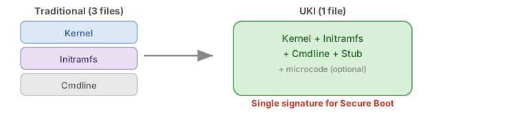
One file is easier to replace atomically and to sign: with Secure Boot, a single signature covers the kernel, the initrd and the command line, which can then no longer be changed at boot. That fits image-based systems, where the boot files are produced by the build, not by the device.
Inside a UKI
A UKI is a PE/COFF file whose sections hold the parts: the stub code in .text, the kernel in .linux, the initrd in .initrd, the command line in .cmdline, and optionally .osrel for the os-release information, .uname, .splash, .dtb for a device tree on Arm, and .ucode for microcode in recent systemd versions.
systemd-stub and the kernel’s EFI stub

The two stubs are often confused. systemd-stub is the EFI application that the firmware, or a boot loader such as systemd-boot, runs: it finds the sections of the UKI, measures them into the TPM if there is one, and starts the kernel. It does so through the standard UEFI image loading service, so the kernel must still be built with CONFIG_EFI_STUB=y, the EFI stub described above.
Building a UKI
ukify, from systemd, is the tool to use: it lays out and aligns the sections itself, and can sign the result.
ukify build \
    --linux=/boot/vmlinuz-6.6.0 \
    --initrd=/boot/intel-ucode.img \
    --initrd=/boot/initrd.img-6.6.0 \
    --cmdline="root=PARTUUID=4f9b6c1e-02 rw quiet" \
    --os-release=@/etc/os-release \
    --output=/boot/efi/EFI/Linux/linux-6.6.0.efi
Older guides build UKIs with objcopy --add-section and fixed section addresses. That works only as long as each part fits in the space left before the next address, and breaks silently when the kernel or the initrd grows: the addresses have to be computed from the stub’s section alignment, which is what ukify does. Distributions also generate UKIs as part of kernel installation, with kernel-install, dracut --uefi or mkinitcpio.
Inspecting a UKI
Before deploying a UKI, check what went into it. ukify shows the sections and their contents, objcopy extracts one of them, and sbverify lists the signatures:
# Sections, sizes, command line and os-release, in one view
ukify inspect linux.efi

# Extract one section
objcopy -O binary --only-section=.cmdline linux.efi cmdline.txt
objcopy -O binary --only-section=.linux   linux.efi vmlinuz

# Signatures
sbverify --list linux.efi
A UKI goes to /EFI/Linux/, where systemd-boot finds it, or to /EFI/BOOT/BOOTX64.EFI to be started by the firmware with no boot loader at all. Versioned names, such as linux-6.6.0.efi, let several kernels sit side by side.
From Here
The x86 boot has kept its two stages, firmware then boot loader, but each of them has grown: the firmware is now an operating system of its own, with variables Linux can change; ACPI describes the board instead of a device tree; and the boot loader can shrink to nothing when a UKI is started directly. In the next article of this series, we build all of it with Yocto: the boot partition, the microcode and ACPI archives, the UKI, A/B updates with RAUC on top of BootNext, and Secure Boot.
LABCSMART builds and maintains boot chains like these on industrial x86 and Arm products: see our engineering services. The boot chain is also covered, hands-on, in our embedded Linux training.