
The first part of this series followed the ARM64 boot chain from the ROM code to the secure world. None of the programs it met reaches the boot medium as a bare binary: each one travels inside a container, sometimes nested in another, behind the header its reader expects.
This second part covers those containers, the FIT image of U-Boot and the Firmware Image Package (FIP) of Trusted Firmware-A, the chain of trust they carry, the assembly of the final image and the handoff to Linux.
Contents
What Ends Up on the Boot Medium
On an i.MX8M Mini, the boot medium holds a single file called flash.bin, and only half of what it contains comes from U-Boot. The DDR training firmware is supplied by NXP, bl31.bin comes from TF-A and tee.bin from OP-TEE. Each piece sits at an offset imposed by the ROM code or by the SPL, behind the header that its reader expects.
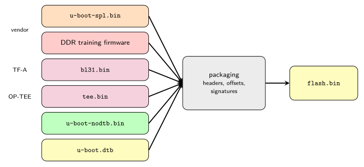
Two container formats carry most of this content: the FIT image, read by U-Boot SPL and U-Boot proper, and the FIP, read by TF-A BL2. As the first part showed, the container follows the first loader, and the SoC vendor chose that loader long before the board existed.
FIT Images: the Flattened Image Tree
U-Boot’s original image format put a 64-byte header in front of a single payload, with a load address, an entry point and a CRC32. It is still around in uImage kernels and boot.scr scripts, and it shows the three problems FIT was designed to solve. A kernel, its device tree and an initramfs were three separate files that nothing tied together. A CRC detects accidental corruption but cannot carry a signature. And one image could not serve several board revisions.
The Flattened Image Tree (FIT) reuses a format U-Boot already parses, the device tree blob. A FIT image is a DTB with two main nodes. /images holds the binaries, each with its type, architecture, compression, load address and hashes. /configurations lists the combinations of those binaries that are allowed to boot together, and names a default one.
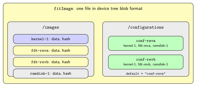
Its source is an ordinary device tree file, with /incbin/ pulling each binary into a data property. A kernel FIT for a product with two board revisions looks like this:
/dts-v1/;
/ {
        description = "Kernel and device trees, two board revisions";
        #address-cells = <1>;

        images {
                kernel-1 {
                        data = /incbin/("Image.gz");
                        type = "kernel";
                        arch = "arm64";
                        os = "linux";
                        compression = "gzip";
                        load = <0x42000000>;
                        entry = <0x42000000>;
                        hash-1 { algo = "sha256"; };
                };
                fdt-reva {
                        data = /incbin/("board-reva.dtb");
                        type = "flat_dt";
                        arch = "arm64";
                        compression = "none";
                        hash-1 { algo = "sha256"; };
                };
                /* fdt-revb is declared the same way */
        };

        configurations {
                default = "conf-reva";
                conf-reva {
                        kernel = "kernel-1";
                        fdt = "fdt-reva";
                };
                conf-revb {
                        kernel = "kernel-1";
                        fdt = "fdt-revb";
                };
        };
};
The kernel is stored once, however many configurations use it, and U-Boot checks every image against its hash before using it. The same file can be installed on both board revisions, with U-Boot picking the configuration at boot time. A compressed arm64 kernel is usually booted this way, since U-Boot unpacks it to its load address itself.
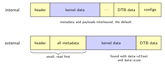
The FIT read by the SPL
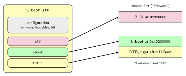
The SPL uses the same format for the boot firmware. On the i.MX8M Mini, the FIT it reads holds U-Boot proper, BL31, an optional OP-TEE and the device tree of U-Boot. Unlike a kernel FIT, where U-Boot could place a device tree by itself, every executable image here has to state its load address, because the SPL has no other source for it:
/ {
        description = "Configuration to load ATF before U-Boot";
        #address-cells = <1>;

        images {
                uboot {
                        description = "U-Boot (64-bit)";
                        data = /incbin/("u-boot-nodtb.bin");
                        type = "standalone";
                        arch = "arm64";
                        compression = "none";
                        load = <0x40200000>;
                };
                atf {
                        description = "ARM Trusted Firmware";
                        data = /incbin/("bl31.bin");
                        type = "firmware";
                        arch = "arm64";
                        compression = "none";
                        load = <0x920000>;
                        entry = <0x920000>;
                };
                tee {
                        description = "OP-TEE";
                        data = /incbin/("tee.bin");
                        type = "tee";
                        os = "tee";
                        arch = "arm64";
                        compression = "none";
                        load = <0xbe000000>;
                        entry = <0xbe000000>;
                };
                fdt-1 {
                        description = "imx8mm-evk";
                        data = /incbin/("u-boot.dtb");
                        type = "flat_dt";
                        compression = "none";
                };
        };

        configurations {
                default = "config-1";
                config-1 {
                        firmware = "uboot";
                        loadables = "atf", "tee";
                        fdt = "fdt-1";
                };
        };
};
This is the description mainline U-Boot generates for the i.MX8M Mini, slightly abridged. BL31 goes to 0x920000 in on-chip RAM, U-Boot to 0x40200000 at the start of the DDR, and OP-TEE to 0xbe000000 at the top of the 2 GiB of the EVK, the regions shown in the first part. The SPL copies each image to its load address and needs one entry point to jump to. U-Boot, listed as firmware, has none, so the SPL takes the first one it finds among the loadables, which is BL31’s. BL31 then starts OP-TEE and U-Boot at the addresses built into its i.MX8M port, as the first part explained. Rockchip boards list BL31 as firmware instead and pass it the other entry points; the container is the same, the convention differs.
Signed FIT images
A hash only proves that the data matches the hash. Whoever replaces a kernel can replace its hash too. A signature proves who built the image: the build signs it with a private key that never leaves the manufacturer, and U-Boot checks it against the public key stored in its own device tree. U-Boot calls this verified boot.
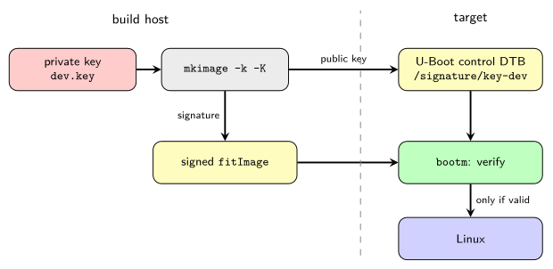
The signature goes into the configuration, not into each image:
conf-reva {
        kernel = "kernel-1";
        fdt = "fdt-reva";
        signature-1 {
                algo = "sha256,rsa2048";
                key-name-hint = "dev";
                sign-images = "kernel", "fdt";
        };
};
A signature placed in an image node would leave two holes. It covers the data of that image only, so its load address, entry point and compression could be changed without breaking it. And nothing would tie the images together: an old, vulnerable kernel paired with a current device tree, both authentic, would pass. A configuration signature closes both. It covers the configuration node, the nodes of the images listed in sign-images with every property except data, and their hash nodes. The data is protected through its hash: U-Boot checks the signature of the selected configuration first, then the hash of each image it loads. The signer records the paths it covered in a hashed-nodes property of the signature node, so that the verifier rebuilds exactly the same regions.
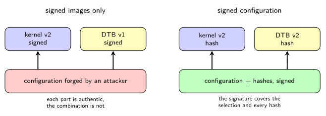
The public key sits in the device tree of U-Boot, under /signature, and its required = "conf" property makes a signed configuration mandatory for every boot. That device tree must in turn be authenticated by the stage before, or the key can simply be replaced. The other doors are closed as well: the old image format and the unverified boot commands are disabled, and the environment is locked. On x86, UEFI Secure Boot fills the same role, which our article on Secure Boot and A/B updates with Yocto and RAUC covers.
FIP: the Firmware Image Package of TF-A
TF-A BL2 has to load BL31, BL32 and BL33 after it has set up the DDR, plus configuration files for some of them. TF-A groups them in a Firmware Image Package (FIP): one file with a table of contents followed by the payloads, found by BL2 in a named partition or at an offset fixed by the platform. On every SoC without an SPL, U-Boot proper is one of these payloads.
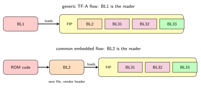
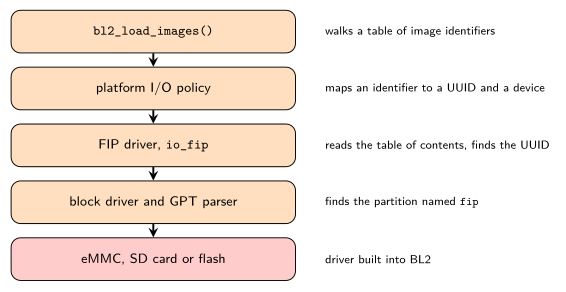
BL2 reads the package with its own drivers. A platform policy maps each image to a storage device and a UUID, the FIP driver walks the table of contents, and each image is copied to an address that the platform code knows. BL2 then hands the list of loaded images to BL31.
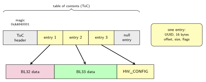
That last point is the main structural difference with FIT. A FIT image says where each payload goes; a FIP leaves it to the TF-A platform code. The usual entries are:
| Entry | TF-A name | Typical content |
|---|---|---|
tb-fw | BL2 | only when BL1 loads BL2 from the FIP |
soc-fw | BL31 | the EL3 runtime firmware |
tos-fw | BL32 | OP-TEE |
nt-fw | BL33 | U-Boot proper |
hw-config | HW_CONFIG | the device tree of U-Boot |
fw-config | FW_CONFIG | addresses and options for BL2 |
The prefixes stand for trusted boot, SoC, trusted OS and non-trusted firmware. U-Boot’s device tree travels as an entry of its own, and BL2 passes its address to U-Boot in a register.
Where a FIP keeps its addresses
Since a FIP entry carries no address, the description of where each image goes lives elsewhere. Older TF-A ports hard-code it in the C code of the platform. Recent ones put it in FW_CONFIG, a small device tree read through the firmware configuration framework that travels as an entry of the FIP and that BL2 reads before anything else. On the STM32MP15, it reads as follows (abridged):
/ {
        dtb-registry {
                compatible = "fconf,dyn_cfg-dtb_registry";

                hw-config {
                        load-address = <0x0 STM32MP_HW_CONFIG_BASE>;
                        max-size = <STM32MP_HW_CONFIG_MAX_SIZE>;
                        id = <HW_CONFIG_ID>;
                };

                nt_fw {
                        load-address = <0x0 STM32MP_BL33_BASE>;
                        max-size = <STM32MP_BL33_MAX_SIZE>;
                        id = <BL33_IMAGE_ID>;
                };

                tos_fw {
                        load-address = <0x0 STM32MP_OPTEE_BASE>;
                        max-size = <STM32MP_OPTEE_SIZE>;
                        id = <BL32_IMAGE_ID>;
                };
        };

        st-mem-firewall {
                compatible = "st,mem-firewall";
                memory-ranges = <
                        DDR_NS_BASE DDR_NS_SIZE TZC_REGION_S_NONE TZC_REGION_NSEC_ALL_ACCESS_RDWR
                        DDR_SEC_BASE DDR_SEC_SIZE TZC_REGION_S_RDWR 0
                        >;
        };
};
Each node of the registry ties an image identifier, the one the FIP maps to a UUID, to a load address and a maximum size that BL2 checks before copying. The values are macros from the platform headers, resolved when TF-A is built for a given board and DDR size. The second node goes further than FIT ever does: it describes how the TrustZone memory controller splits the DDR, all non-secure except the region at the top reserved for OP-TEE, the same region that Linux must later see as reserved memory.
So a FIP platform describes its firmware in two places, the package for what is there and FW_CONFIG for where it goes, where a FIT source holds both.
A FIP platform: STM32MP15
On an STM32MP15 board, the storage layout shows both readers at work. The ROM code finds BL2 by partition name in fsbl1, or in fsbl2 if the first copy is damaged. BL2 then finds the FIP, also by name, in the fip partition, and starts OP-TEE, then U-Boot. The first part shows how the BL2 file is built.
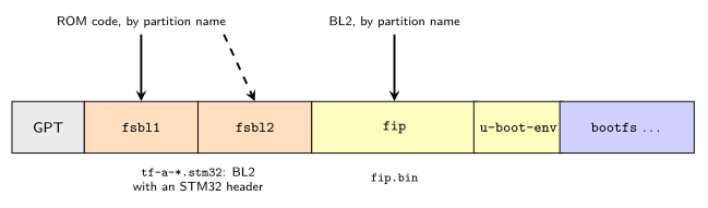
Updating U-Boot on such a board rewrites the fip partition only, without touching the two BL2 copies.
The Chain of Trust
TF-A authenticates the entries of a FIP with X.509 certificates, a scheme it calls Trusted Board Boot. The certificates are entries of the package themselves. Each one holds the hash of an image and is signed by a key of the chain, whose root hash is burnt into the fuses of the SoC, so BL2 verifies BL31, OP-TEE and U-Boot before starting any of them.
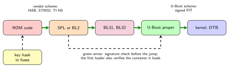
SoCs with an SPL build the same chain from other parts. The ROM code checks the SPL with the vendor scheme: HAB on i.MX8M, the EdgeLock Enclave on i.MX 9, the X.509 certificates of TI HS devices. The SPL checks a signed FIT holding BL31, OP-TEE and U-Boot, and U-Boot checks the signed FIT of the kernel. In both cases the ROM code is the only stage trusted without a check. Burning the key hash and closing the part cannot be undone, which is why it usually happens on the production line, as described in our article on factory manufacturing for i.MX6 and i.MX8.
FIT and FIP Side by Side
The two formats answer the same need for two different loaders.
| FIP | FIT | |
|---|---|---|
| Defined by | Trusted Firmware-A | U-Boot |
| Structure | binary table of UUIDs | device tree blob |
| Read by | TF-A BL2 (or BL1) | U-Boot SPL, U-Boot proper |
| Load addresses | in the platform code or FW_CONFIG | in the image |
| Authentication | X.509 certificates | signature nodes |
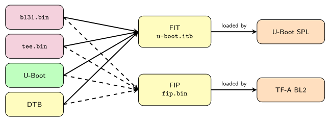
The payloads are identical either way, and moving a SoC from one model to the other would not change U-Boot proper. Much of the confusion comes from the kernel side: a FIP platform still boots its kernel from a FIT, because the firmware container and the kernel container are two separate decisions.
Assembling the Final Image
A real boot image nests these containers at precise offsets, inside the header the ROM code wants. Each vendor long had its own script for that step, such as imx-mkimage for NXP, with offsets duplicated between the script and the bootloader configuration. Mainline U-Boot now does it during its own build with binman, which reads a description of the image from U-Boot’s device tree and calls the right tools for each part.
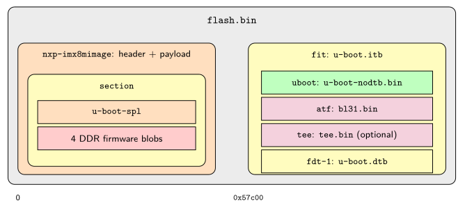
The map that binman writes next to the image is the first file we open when a board does not boot, because it shows where each part actually landed:
ImagePos    Offset      Size  Name
00000000  00000000  00134800  image
00000000  00000000  00036e00      nxp-imx8mimage
00000000  00000000  0002e3b8          u-boot-spl
0002e3b8  0002e3b8  00008000          ddr-1d-imem-fw
00057c00  00057c00  000dcc00      fit
000582e8  000006e8  000cee28        uboot
00127110  000cf510  0000a009        atf
00131119  000d9519  0000acd8        fdt-1
The FIT starts at 0x57c00 in the file. Since the file itself is written at 33 KiB on the card, the FIT lands at sector 0x300, which is exactly where the SPL looks for it. When one of the two numbers changes without the other, the SPL prints failed to boot from all boot devices.
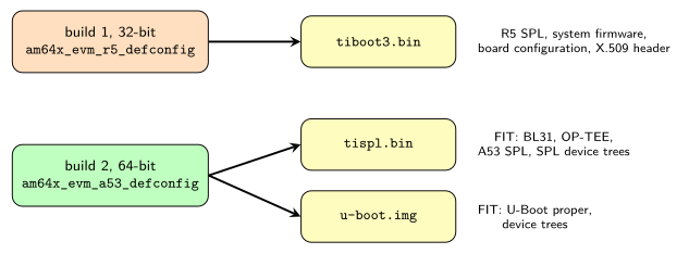
The AM64x needs three files instead of one, produced by two separate builds of U-Boot, for the R5 and for the A53. The build signs each of them with the certificates that the TI ROM code and the SPL expect.
In a Yocto build, the U-Boot recipe depends on TF-A, OP-TEE and the vendor firmware, and hands their deployed files to the U-Boot build, so the final image comes out of a single bitbake run.
The Handoff to Linux
When the bootloader starts the kernel, the DRAM is trained, storage works and the secure firmware is resident. What remains is to place the kernel, its device tree and an optional initramfs in DRAM, write the command line, adjust the device tree and jump. U-Boot, barebox and a UEFI firmware followed by GRUB all end with the same steps; the examples below use U-Boot.
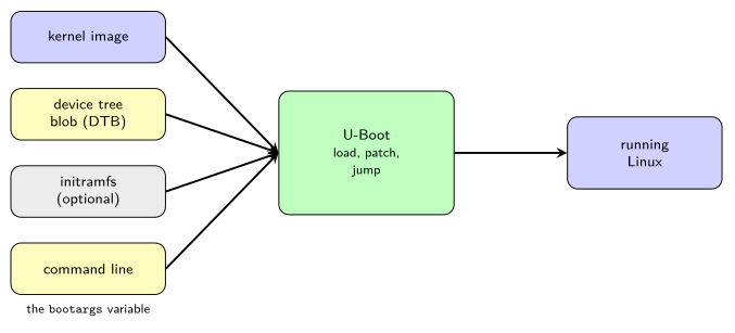
The arm64 boot protocol fixes the state of the CPU at the kernel entry point: the device tree address in register x0, zero in x1 to x3, the MMU and data cache off, interrupts masked, the CPU at EL2 or EL1. The arm64 Image starts with a small header that gives the memory size the kernel needs. Unlike a 32-bit zImage, it does not decompress itself, so U-Boot either loads it as is or unpacks a compressed one first. A manual boot from the U-Boot prompt shows the sequence:
u-boot=> load mmc 1:1 ${kernel_addr_r} Image
u-boot=> load mmc 1:1 ${fdt_addr_r} imx8mm-evk.dtb
u-boot=> setenv bootargs console=ttymxc1,115200 root=/dev/mmcblk1p2 rootwait
u-boot=> booti ${kernel_addr_r} - ${fdt_addr_r}
## Flattened Device Tree blob at 48000000
   Booting using the fdt blob at 0x48000000
   Loading Device Tree to 00000000bcf0f000, end 00000000bcf1dfff ... OK
Starting kernel ...
Starting kernel ... is the last line U-Boot prints, and anything after it comes from Linux. Before that line, U-Boot has already moved the device tree: it copies it near the top of the memory and makes room in it, since it is about to add data.
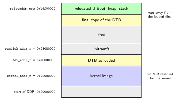
The load addresses must not overlap, including the memory the kernel uses beyond the size of its file. A device tree overwritten by the kernel gives a silent hang.
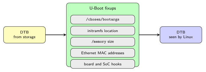
The kernel never sees the device tree exactly as it was built. The bootloader fills in the memory size, the command line, the initramfs location, the MAC addresses and the reserved memory of the secure world. /proc/device-tree on the running system shows the result.
How Recent SoCs Rearrange the Chain
The three chains of the first part cover most SoCs in production. Two recent parts we have worked on rearrange them.
NXP i.MX943. A Cortex-M33 starts first. Its ROM code runs the OEI, which trains the LPDDR, then the System Manager, which owns every clock, power domain and reset of the chip. Only then are the Cortex-A55 cores released, and every stage on them, from SPL to Linux, asks the System Manager for its clocks through SCMI. Everything before Linux ships in one flash.bin made of two containers, both authenticated by the EdgeLock Enclave. We brought it up with mainline U-Boot for a maker of industrial equipment.
Renesas RZ/G3E. There is no SPL. The ROM code starts TF-A BL2 from bl2_bp_mmc.bin, as the first part described, and BL2 reads fip.bin with BL31, an optional OP-TEE and U-Boot. Our upstream kernel work on this SoC runs on top of that chain.
In a further article, we will follow the chain when it breaks: how the last line on the console points at the stage that stopped, and what we check at each one.